The Most Trusted Name In Measurement
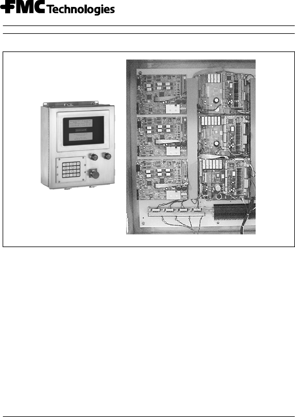
Electronic Preset Delivery System
Smith Meter
AccuLoad
III-SA
Installation Manual
Bulletin MN06140
Issue/Rev. 0.6 (8/15)
Caution
The default or operating values used in this manual and in the program of the AccuLoad III are
for factory testing only and should not be construed as default or operating values for your metering
system. Each metering system is unique and each program parameter must be reviewed and
programmed for that specific metering system application.
Disclaimer
FMC Technologies Measurement Solutions, Inc. hereby disclaims any and all responsibility for
damages, including but not limited to consequential damages, arising out of or related to the
inputting of incorrect or improper program or default values entered in connection with
the AccuLoad III.

i
Receipt of Equipment
When the equipment is received the outside packing case should be checked immediately for any shipping damage.
If the packing case has been damaged, the local carrier should be notified at once regarding his liability. Carefully
remove the unit from its packing case and inspect for damaged or missing parts.
If damage has occurred during shipment or parts are missing, a written report should be submitted to the Customer Ser-
vice Department, FMC Technologies Measurement Solutions Inc., 1602 Wagner Avenue, Erie, Pennsylvania 16510.
Prior to installation, the unit should be stored in its original packing case and protected from adverse weather
conditions and abuse.
Caution:
This equipment generates, uses, and can radiate radio frequency energy and, if not installed and used in
accordance with this Instruction Manual, may cause interference to radio communications. It has not
been tested to comply with the limits for a Class A computing device pursuant to Subpart J of Part 15 of
FCC Rules, which are designed to provide reasonable protection against such interference when operated in a
commercial environment. Operation of this equipment in a residential area is likely to cause interference, in
which case the user, at his own expense, will be required to take whatever measures may be required to
correct the interference.
Warning
These preset devices must be used with fail-safe backup equipment to prevent accidental runaway
delivery of product. Failure to provide backup equipment could result in personal injury, property loss
and equipment damage.
On initial power-up of a new unit or after installation of a new computer board, there are several alarms
that will be triggered which cannot be cleared until the AccuLoad is programmed.
United States NIST Handbook 44 UR.3.5.1. and UR.3.5.2.
For compliance to United States NIST Handbook 44 UR.3.5.1. and UR.3.5.2., invoices printed using a mechanical
numeric-only printer (e.g., Smith Load Printer) must contain in preprinted form the following information:
a. Volume corrected to 60 degrees F
b. API/C of E _____________________
c. Temperature ____________________
d. Gross Volume ____________________
where the API/C of E, temperature, and gross volume may be hand-written on the ticket. Refer to Handbook 44,
UR.3.5.1. and UR.3.5.2. for current requirements.

Table of Contents
ii
Section I - Introduction ........................................................................................................................ 1
Receipt of Equipment ....................................................................................................................... 1
Section II - Pre-Installation Considerations .......................................................................................... 2
Mechanical ....................................................................................................................................... 2
Electrical .......................................................................................................................................... 2
Section III - Installation ........................................................................................................................ 4
Mechanical ....................................................................................................................................... 4
Electrical .......................................................................................................................................... 4
Installing and Removing the Analog I/O Module ............................................................................... 4
Input Frequency x2 .......................................................................................................................... 5
Start-Up Procedure .......................................................................................................................... 5
Section IV - Diagrams ......................................................................................................................... 6
Analog Module Settings (JP1 on EAAI) .......................................................................................... 12
Bi-State DC Inputs and Output Jumper Settings (JP1 on the BSE) ................................................ 14
Pulse Inputs (One Board Set) ........................................................................................................ 17
Dual Pulse Inputs for Rev. 10.07 and Above Firmware (With Flow Controlled Additive) ................. 18
Promass 80, 83 and 84 Modeling (Single & Dual Pulse Wiring) ..................................................... 32
Wiring Terminals, 4-20mA and 1-5 Vdc Inputs/Outputs (One Board Set) ....................................... 45
Digital Inputs .................................................................................................................................. 46
Wiring Terminals, Digital Inputs (One Board Set) ........................................................................... 47
Digital Outputs ............................................................................................................................... 48
Wiring Terminals, Digital Outputs (One Board Set) ........................................................................ 49
Optional AICB Board (Additive Inputs/Outputs) (Per Board Set) .................................................... 67
Communications (AICB Boards) .................................................................................................... 69
Jumper Locations ........................................................................................................................... 69
Digital Inputs – AICB ...................................................................................................................... 75
Section V - Specifications .................................................................................................................. 78
Specifications (AccuLoad III) .......................................................................................................... 78
Accuracy ........................................................................................................................................ 78
Weight ........................................................................................................................................... 78
Electrical Inputs (Per Board Set) .................................................................................................... 78
Electrical Outputs (Per Board Set) ................................................................................................. 79
Environment ................................................................................................................................... 79
Communications (Per Board Set) ................................................................................................... 80
Specifications (AICB Board - Optional) .......................................................................................... 80
Specifications (Red and Green Indicating Light Units - Optional) ................................................... 81
Specifications (Stop Button - Optional) ........................................................................................... 81
Section VI - Related Publications ...................................................................................................... 79

Table of Contents
iii
Figure 1. Analog Modules .................................................................................................................... 4
Figure 2. Connector and Switches on PIB Board .................................................................................. 5
Figure 3. MMI Dimensions .................................................................................................................... 6
Figure 4. Flow Control Module Dimensions .......................................................................................... 7
Figure 5. AccuLoad III-SA Board Layout Photograph ........................................................................... 8
Figure 6. AccuLoad III-SA Board Layout Diagram ................................................................................ 9
Figure 7. KDC Layout ......................................................................................................................... 10
Figure 8. EAAI Layout ........................................................................................................................ 11
Figure 9. BSE Layout ......................................................................................................................... 13
Figure 10. KDC/EAAI/PIB/BSE Boards (One Board Set) .................................................................... 15
Figure 11. PIB Boards (One Board Set) ............................................................................................. 16
Figure 12. MMI Wiring Diagram .......................................................................................................... 22
Figure 13. Wiring Diagram, Prime 4 Meter Single Pulse (One Board Set) .......................................... 23
Figure 14. Wiring Diagram, Prime 4 Meters Dual Pulse (One Board Set) ........................................... 24
Figure 15. Wiring Diagram, Genesis Meter Single Pulse (One Board Set) ......................................... 25
Figure 16. Wiring Diagram, Genesis Meter Dual Pulse (One Board Set) ............................................ 26
Figure 17. Wiring Diagram, PEX-P Transmitter Single Pulse (One Board Set) ................................... 27
Figure 18. Wiring Diagram, PPS Transmitters Single Pulse (One Board Set) ..................................... 28
Figure 19. Wiring Diagram, PPS Dual Pulse Transmitter (One Board Set) ......................................... 29
Figure 20. Wiring Diagram, Turbine Meters with PA-6 Pre-amps Single Pulse (One Board Set) ........ 30
Figure 21. Wiring Diagram, Dual Pulse Turbine Meters with PA-6 Pre-amps (One Board Set) ........... 31
Figure 22. Wiring Diagram, Promass Single Pulse (One Board Set) .................................................. 33
Figure 23. Wiring Diagram, Promass Dual Pulse (One Board Set) ..................................................... 34
Figure 24. Wiring Diagram, Optically Isolated Open Collector Output (One Board Set) ...................... 35
Figure 25. Wiring Diagram, GPST Dual Pulse Transmitter + 24 Vdc
with Open Collector Output with Common Ground ............................................................ 36
Figure 26. Wiring Diagram, GPST Dual Pulse Transmitter + 12 Vdc
with Open Collector Output with Common Ground Converter P2412 see MN06117 .......... 36
Figure 27. Wiring Diagram, Four Additive Meters, Active Outputs (One Board Set) ............................ 37
Figure 28. Typical Additive Feedback Wiring ...................................................................................... 38
Figure 29. Monoblock to AICB Wiring Diagram .................................................................................. 39
Figure 30. Monoblock to PIB Wiring Diagram ..................................................................................... 39
Figure 31. Wiring Diagram, High Speed Prover Output (Open Collector Opto Coupler) ..................... 40
Figure 32. Resistance (RTD) Input (One Board Set) .......................................................................... 41
Figure 33. AC Remote Start and Stop ................................................................................................ 42
Figure 34. DC Remote Start and Stop ................................................................................................ 42
Figure 35. 4-20mA Inputs (Active) ...................................................................................................... 43
Figure 36. 4-20mA Inputs (Passive) ................................................................................................... 43
Figure 37. 4-20mA Outputs ................................................................................................................ 44
Figure 38. 1-5 Vdc Input ..................................................................................................................... 44
Figure 39. 1-5 Vdc Output .................................................................................................................. 45
Figure 40. DC Inputs .......................................................................................................................... 46
Figure 41. AC Inputs .......................................................................................................................... 46
Figure 42. DC Outputs ....................................................................................................................... 48
Figure 43. AC Outputs ........................................................................................................................ 48
Figure 44. KDC Typical Diagram (One Board Set in FCM) ................................................................. 51
Figure 45. 24Vdc Terminal Block Diagram ......................................................................................... 52
Figure 46. Pump and Block Valve Wiring Diagram ............................................................................. 53
Figure 47. Typical Block Valve Feedback Wiring ................................................................................ 54
Figure 48. Pump and Alarm Contact Wiring........................................................................................ 55
Figure 49. MMI to FCM RS232 Comm Port Wiring (With Four Board Sets) ........................................ 56
Figure 50. MMI to FCM 485 Comm Port Wiring (With Four Board Sets) ............................................. 57
Figure 51. Dual MMI 485 Comm Port Wiring (With Four Board Sets) ................................................. 58
Figure 52. EIA-232 Multi-Drop Communications ................................................................................. 59

Table of Contents
iv
Figure 53. EIA-485 Multi-Drop Communications ................................................................................. 60
Figure 54. Network Configuration for Multiple AccuLoads .................................................................. 61
Figure 55. Lubrizol EIA-232 Communications (One Board Set) .......................................................... 62
Figure 56. Lubrizol EIA-485 (Two-Wire) Communications (One Board Set) ........................................ 63
Figure 57. EIA-485 (Four-Wire) Additive Communication (Lubrizol Blend-Pak) (One Board Set) ........ 64
Figure 58. EIA-485 (Four-Wire) Additive Communication (Titan Pac3) (One Board Set) .................... 65
Figure 59. Typical Six-Arm Straight Product Loading (One Board Set). ................................................. 66
Figure 60. Optional AICB Board. ........................................................................................................ 71
Figure 61. AICB Jumper Locations. .................................................................................................... 72
Figure 62. AICB Communications and DC Power............................................................................... 73
Figure 63. AICB Communications (Two-wire RS-485) ........................................................................ 74
Figure 64. Metered Injector / Pulse Transmitter Wiring Diagram. ........................................................ 75
Figure 65. Metered Injector / Open Collector Wiring Diagram. ............................................................ 75
Figure 66. Metered Injector / Contact Closure Wiring Diagram ........................................................... 76
Figure 67. AICB Additive Outputs ....................................................................................................... 77

Section I – Introduction
MN06140 Issue/Rev. 0.6 (8/15) 1
This manual is to be used for the installation of the
AccuLoad III Electronic Preset Controller with Accu-
Load III-SA firmware. The manual will be divided into
six sections: Introduction, Pre-Installation Considera-
tions, Installation, Diagrams, Specifications, and Re-
lated Publications.
“Pre-Installation Considerations” describes the areas
that must be considered prior to the installation of
the AccuLoad III.
“Installation” describes the areas that have to be
considered when installing the AccuLoad III.
“Diagrams” covers dimensional outline drawings,
wiring schematics, etc.
“Specifications” describes the specifications of the
AccuLoad III Electronic Preset.
“Related Publications” lists the literature that is
associated with the AccuLoad III-SA.
Receipt of Equipment
When the equipment is received the outside packing
case should be checked immediately for any shipping
damage. If the packing case has been damaged, the
local carrier should be notified at once regarding his
liability. Carefully remove the unit from its packing
case and inspect for damaged or missing parts.
If damage has occurred during shipment or if parts
are missing, a written report should be submitted to
the Customer Service Department, FMC Technologies
Measurement Solutions, Inc., 1602 Wagner Avenue,
Erie, Pennsylvania 16510.
Before installation, the unit should be stored in its
original packing case and protected from adverse
weather conditions and abuse.
Section II – Pre-Installation Considerations
2 MN06140 Issue/Rev. 0.6 (8/15)
Mechanical
In addition to the following, all previous warnings
and cautions should be reviewed before installation.
1. A solid base (pedestal or shelf) should be used to
support the AccuLoad III Man Machine Interface
(MMI) housing.
2. The location and the height of the AccuLoad III
should be selected to permit easy viewing of the
display and to provide convenient access to the
keypad by all users.
3. Access for servicing the AccuLoad III is through
the front cover. For ease of service and removal
of parts the cover must swing open more than
90. The AccuLoad III is hinged on the left.
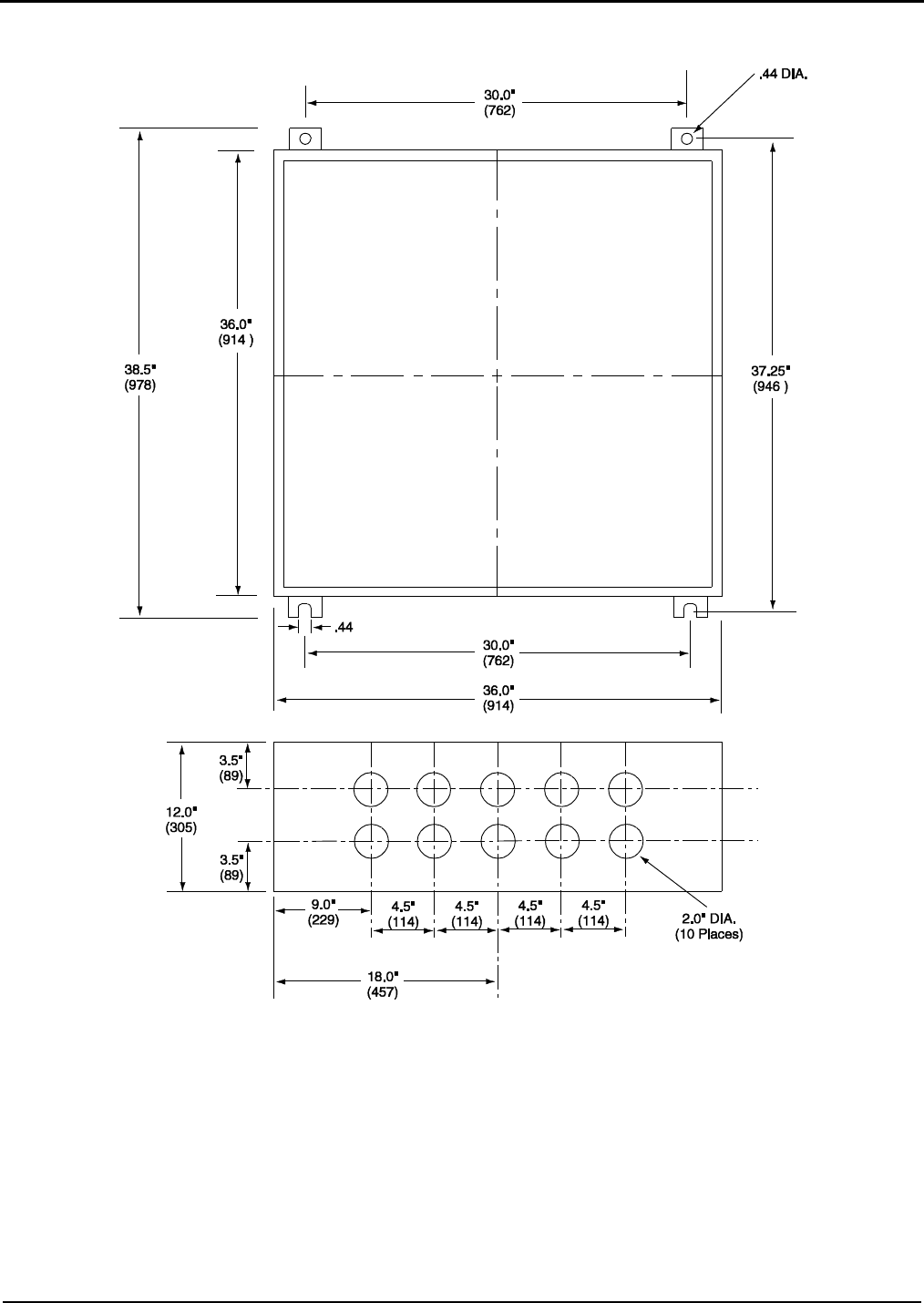
4. All wiring is through the conduit entrances located
on the bottom of the NEMA IV housing. There
are three 1.75" conduit entrances in the MMI
and ten 2.00" conduit entrances in the Flow
Control Module (FCM).
5. A din rail is mounted in the lower section of the
FCM housing. The din rail has connectors to dis-
tribute the 24 Vdc power to the transmitters
mounted on the meters. The din rail also pro-
vides for up to 50 1-amp fused disconnect lever
terminal blocks.
6. In warm climates, the AccuLoad III should be
shaded from direct sunlight. The maximum ex-
ternal temperature of the AccuLoad III housing
must not exceed 140°F (60°C) to ensure that the
internal temperature limit is not exceeded.
Electrical
1. Caution: Each board set should be handled
individually and contains its own “unique”
24v DC power supply. All external devices
such as pulse transmitters, RTD’s, 4-20mA
devices and communication wiring that inter-
face with a board set MUST be powered by
the +24VDC supplied by that board set and all
the grounds including shield wires must be
connected/isolated to that board set, includ-
ing the associated +24VDC distribution block.
A sharing of power supplies and grounding
between board sets can cause ground loops
leading to communication problems, external
device issues and instability of the DC power
supply output from the EAAI board.
2. All DC wiring must be routed into AccuLoad III
through the conduit entries located in the bottom
of the housing. Do not route DC and AC wiring
through the same conduit entry. DC wiring must
use internal DC wiring ducts.
3. The DC signal wires must be multi-conductor
shielded cables of 18 to 24 AWG minimum strand
copper.
Note: The following recommendations are based on our
knowledge of the electrical codes. The local electrical codes should
be reviewed to ensure that these recommendations follow the local
code. Also installation manuals of all the equipment being wired into
the AccuLoad should be reviewed for transmission distances and
wire recommendations.
Table 1. Typical Wire Sizes
Equipment
Number and
Gauge of
Wire
Belden
Number or
Equivalent
Transmitters
4 / 18 Ga.
4 / 20 Ga.
9418
8404
Temp. Probes
Density & Pressure
Transmitters
4 / 22 Ga.
8729
OR
9940
EIA-232
Communications
3 / 24 Ga.
9533
EIA-485
Communications
4 / 24 Ga.
9842
Table 2. Maximum Cable Length and Baud Rate
(EIA-232)
Baud Rate
Feet
Meters
38,400
250
75
19,200
500
150
9,600
1,000
305
4,800
2,000
610
2,400
4,000
1,220
1,200
4,000
1,220
Table 3. Maximum Cable Length and Baud Rate
(EIA-485)
Baud Rates
Feet
Meters
1,200 to
38,400
4,000
1,220

Section II – Pre-Installation Considerations
MN06140 Issue/Rev. 0.6 (8/15) 3
Note: For Ethernet communications, refer to IEEE and IT rules,
regulations, and procedures regarding transmission distances
when connecting to any hub, router, switch, etc.
3. All AC wiring must be routed into the AccuLoad
III through the conduit entries located in the bot-
tom of the housing. Connectors are sized for a
maximum of 14 gauge wire. Consult the local
electrical codes for the minimum AC wire size
required for your application. Do not route AC
and DC wiring through the same conduit entry.
AC wiring must use AC wiring ducts.
4. All AC wiring should be stranded copper and
must comply with federal, state and local codes
and specifications.
5. Two separate AC circuits must be provided from
the breaker panel. One circuit will supply isolated
power to the AccuLoad III electronics (instru-
ment power). The second circuit will supply
power to the external devices.
6. For proper operation the AccuLoad III must be
earth grounded. The grounding point should be as
close to the unit as possible. To ensure proper
earth ground, the following conditions must be met:
a) The resistance between the earth ground
terminal in the AccuLoad III and the ground-
ing point must not exceed 2 Ω
b) The proper grounding point is a ½" to ¾" di-
ameter copper stake that extends into the
water table. Where this is not practical, a
ground plane may be used;
Note: Electrical conduit, piping, and structural steel are
not considered proper grounding points for equipment
using electronics.
c) No other devices, except AccuLoad IIIs and
ancillary equipment such as load printers,
should be connected to any point in the
grounding circuit.
7. If external relay permissives are used in series
with AccuLoad III relays, an RC network must be
placed in parallel with the permissive to prevent
a false turn-on of the AccuLoad III relays. Rec-
ommended RC network = 0.1 UF capacitor and
a 680 Ω resistor (Electrocube part number RG
2031-11).
8. Interposing relays must be installed between the
pump controller, alarming device, and the Accu-
Load III permissive sense relays.
Important Electrical Safety Installation
Notes
Input and output wiring must be in accordance with
Class I, Division 2 wiring methods and in accordance
with the authority having jurisdiction.
This equipment is suitable for use in Class I, Div. 2,
Groups C and D or non-hazardous locations only.
WARNING – Explosion Hazard – substitution of
components may impair suitability for Class I, Div. 2.
WARNING – Explosion Hazard – do not disconnect
equipment unless power has been switched off
or the area is known to be non-hazardous.
WARNING – EXPLOSION HAZARD. DO NOT
REMOVE OR REPLACE FUSE UNLESS POWER HAS
BEEN DISCONNECTED OR THE AREA IS KNOWN
TO BE FREE OF IGNITABLE CONCENTRATIONS OF
FLAMMABLE GASES OR VAPORS.
The end-use installation must include a switch, suit-
able for the location where it is installed, so that
power can be removed for replacement of fuse.
Section III – Installation
4 MN06140 Issue/Rev. 0.6 (8/15)
Mechanical
See Pre-installation Considerations.
Electrical
1. AC circuits must be isolated from DC circuits
and brought into the unit through their respective
conduit openings.
2. All signal and DC wiring should be connected
before connecting AC wiring.
3. Be sure that all connections on the terminal
blocks are tight.
4. All shields must be connected as follows:
(a) Terminals 3, 13, 14, or 15 on terminal block
TB4 on the EAAI board;
(b) Terminals 3 and 4 on terminal block TB6 on
the KDC board;
(c) Terminals 9 and 10 on TB14 on the BSE
board; or
(d) Terminals 1-12 of P2 on +24Vdc distribution
block.
5. All exposed shields must be properly insulated
to prevent short circuits to other terminals or to
the chassis. The shield at the device (e.g., tem-
perature device, transmitter, etc.) must be cut
back to the insulation and taped off. All shields
should be continuous. If splices are required,
they must be soldered and properly insulated.
6. If other communicating devices are used with
the AccuLoad III, refer to the manual for that unit
for shielding information. Shields for other com-
municating equipment should not be terminated
in the AccuLoad III.
7. Sufficient slack should be provided for the wiring
in the AccuLoad III to permit easy removal of the
boards.
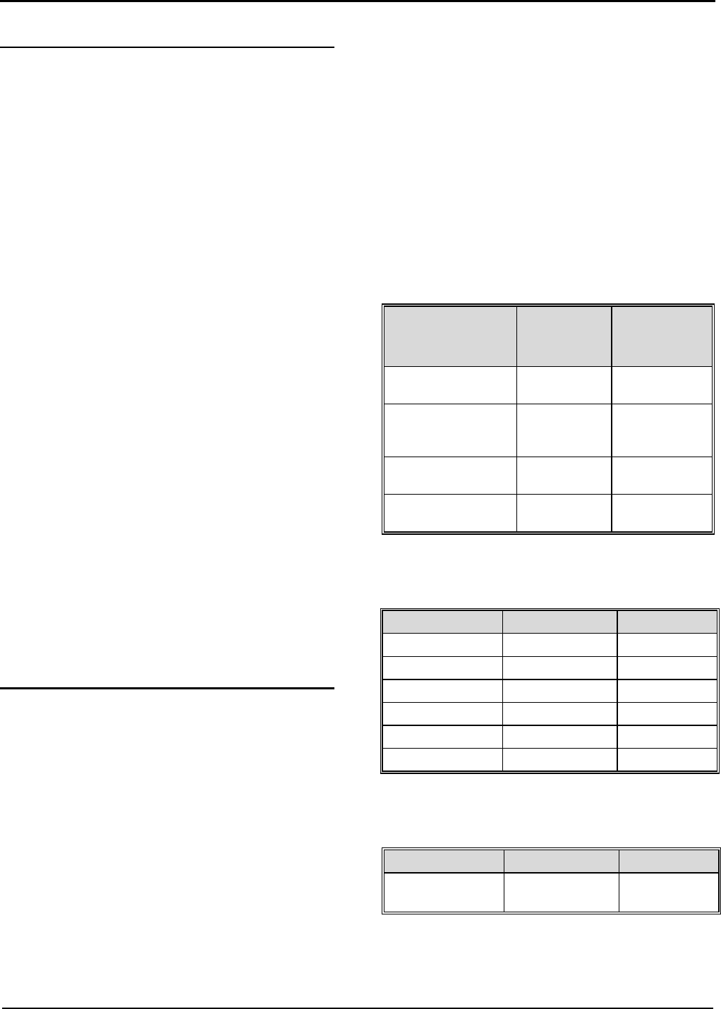
Installing and Removing the Analog I/O Module
Caution: Turn off the power at the unit prior to installing or remov-
ing the Analog I/O Module. Failure to do so will damage modules.
Care should be taken when installing or removing
the Analog I/O modules so as not to damage the
board or the module. To install the module, line up
the alignment pins with the socket and push down
on the module. Once it is seated, screw in the
mounting screw until tight. Do not over-tighten the
screw. To remove the modules from the board, loos-
en the mounting screw and pull up on the module.
Figure 1. Analog Modules
Section III – Installation
MN06140 Issue/Rev. 0.6 (8/15) 5
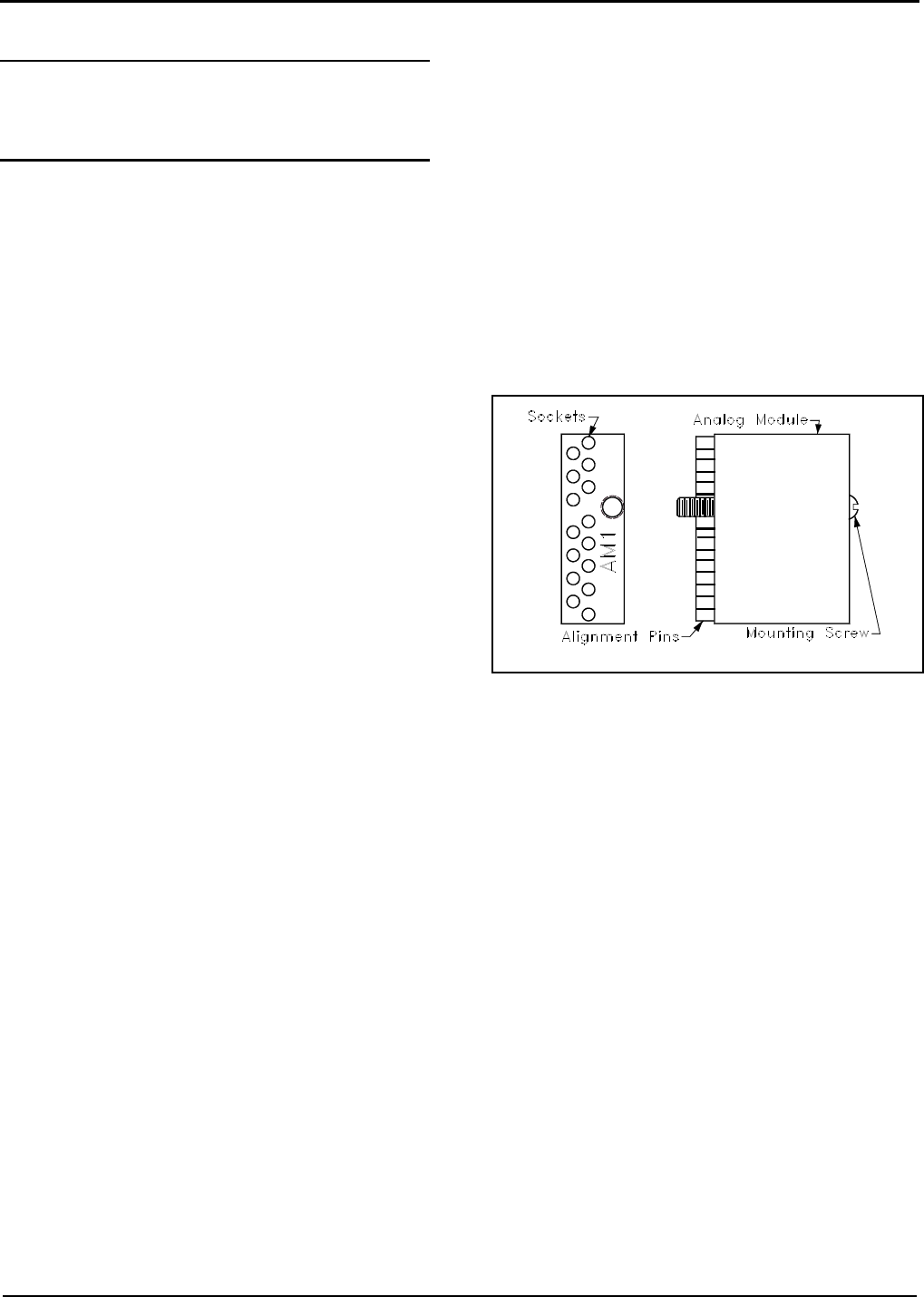
Input Frequency x2
If the application requires a pulse rate that is higher
than the meter is capable of putting out, the Accu-
Load III has the capability of multiplying the incom-
ing pulses times 2. This option is activated by
switches located on the PIB boards. The PIB boards
are located on the EAAI and the BSE boards.
Figure 2. Connector and Switches on PIB Board
The default setting from the factory is "times 1." The
switch is closed (ON). To multiply the incoming puls-
es times 2, push the switch of the incoming pulse
channel to the open (OFF) position. The switches
are located on the PIB boards, as shown in Figure 2
above. The PIB board that is located on the EAAI
board is for pulse inputs 1 through 6. The PIB board
that is located on the BSE board is for pulse inputs 7
through 12.
Note: The switches correspond to the pulse input channels (i.e.,
Meter Pulse In #1 is equal to Switch #1.) See Table 6 for corre-
sponding Pulse Input channels.
Start-Up Procedure
1. Verify that wiring has been completed. Once it is
complete, power can be applied to the unit.
2. The displays should light, indicating that the Ac-
cuLoad is ready for start-up.
3. The AccuLoad can be programmed either
through the keypad or using a PC and the Ac-
cuMate programming tool. Comm port #1 on
each board set is initialized at the factory to
match the communication settings of the Accu-
Mate.
4. Each board set is shipped from the factory with
default addresses 1 through the number of arms
(e.g., if ALX4 firmware, addresses 1 through 4).
5. All board sets on the communication line must
be set up with a unique address for each arm
(e.g., if two board sets are used for eight arms,
each of the eight arms must have a unique ad-
dress).
6. Disconnect all board sets except one from the
comm line that the AccuMate is using until all
the addresses have been programmed as
unique addresses.
7. Once the addresses have all been set as unique
addresses, the comm line can be connected to
all the board sets.
8. Each board set can then be programmed.
9. One comm port on each board set must be con-
figured to communicate with the MMI. It is sug-
gested that this be comm port #2 as indicated in
this manual. Suggested settings for this comm
port are a 38,000 baud rate, 8 bits, and a five-
second time-out.
10. The MMI must be set for MMI function with
matching protocol.
11. Once the programming has been completed and
tested, the system is ready for operation.
12. Record each board set's model and arm ad-
dresses for future reference.
Read the AccuLoad III-SA Operator Reference
Manual, MN06139.
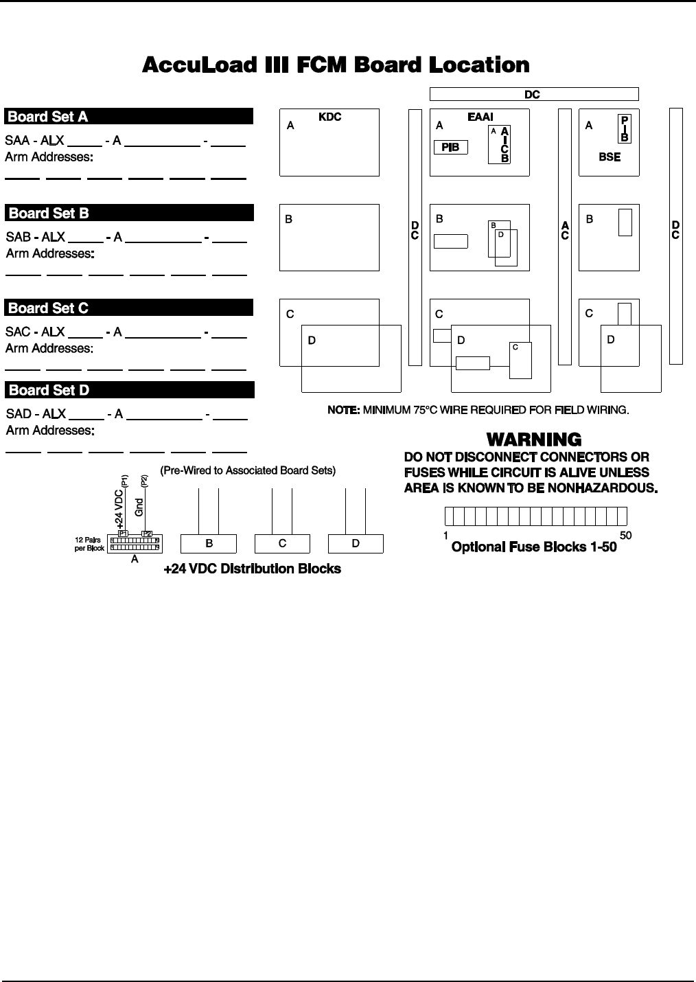
Board Set (A – D)
A set of boards is comprised of one each of the fol-
lowing boards: KDC, EAAI, BSE, and two PIBs.

Section IV – Diagrams
6 MN06140 Issue/Rev. 0.6 (8/15)
Figure 3. MMI Dimensions
Section IV – Diagrams
MN06140 Issue/Rev. 0.6 (8/15) 7
Figure 4. Flow Control Module Dimensions
Section IV – Diagrams
8 MN06140 Issue/Rev. 0.6 (8/15)
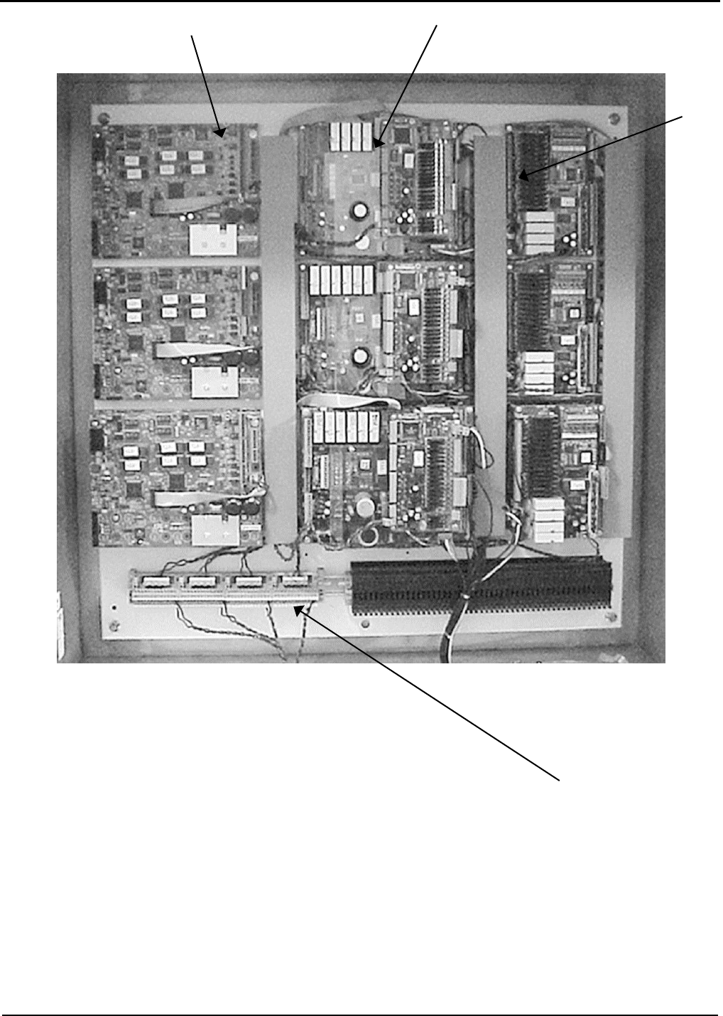
Figure 5. AccuLoad III-SA Board Layout Photograph
BSE
KDC
EAAI
24 Vdc Terminal Blocks
Section IV – Diagrams
MN06140 Issue/Rev. 0.6 (8/15) 9
Figure 6. AccuLoad III-SA Board Layout Diagram
Section IV – Diagrams
10 MN06140 Issue/Rev. 0.6 (8/15)
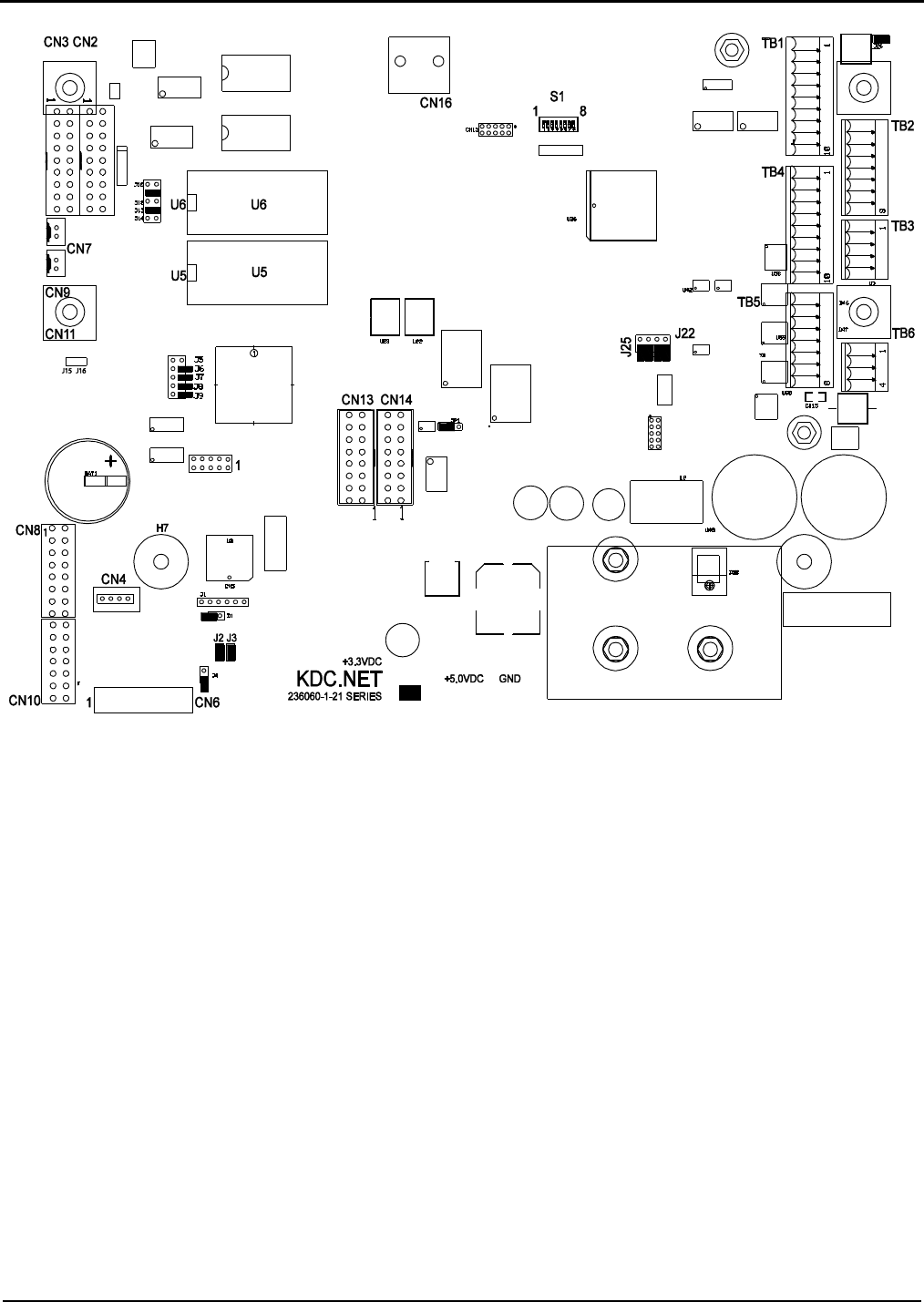
Figure 7. KDC Layout
Configurable jumper locations are heavily circled on the diagram above. It is important to note that all but one of
these jumpers, J22, are factory defaults and should not be configured by the user. The proper settings are provided
below so if one of these is accidentally changed, it can be returned to its original position. J22 is the jumper used
to zero the passcodes. Jumpers are configured using the plugs that fit over the jumper prongs. A jumper with no
prongs plugged, or with one prong plugged, is OUT. A jumper with both prongs plugged is IN.
Note: Should Program Mode be inaccessible after changing PROMs, or if the operator loses or forgets the access code, set J22 to In, then
power up. Entry to the program mode is provided. Check passcodes and remove jumper J22 when finished.
1 – In
4 – Out
7 – Out
10 – Out
13 – In
16 – Out
25 – Out
2 – In
5 – Out
8 – Out
11 – In
14 – Out
23 – In
3 – In
6 – In
9 – Out
12 – Out
15 – In
24 – In
Section IV – Diagrams
MN06140 Issue/Rev. 0.6 (8/15) 11
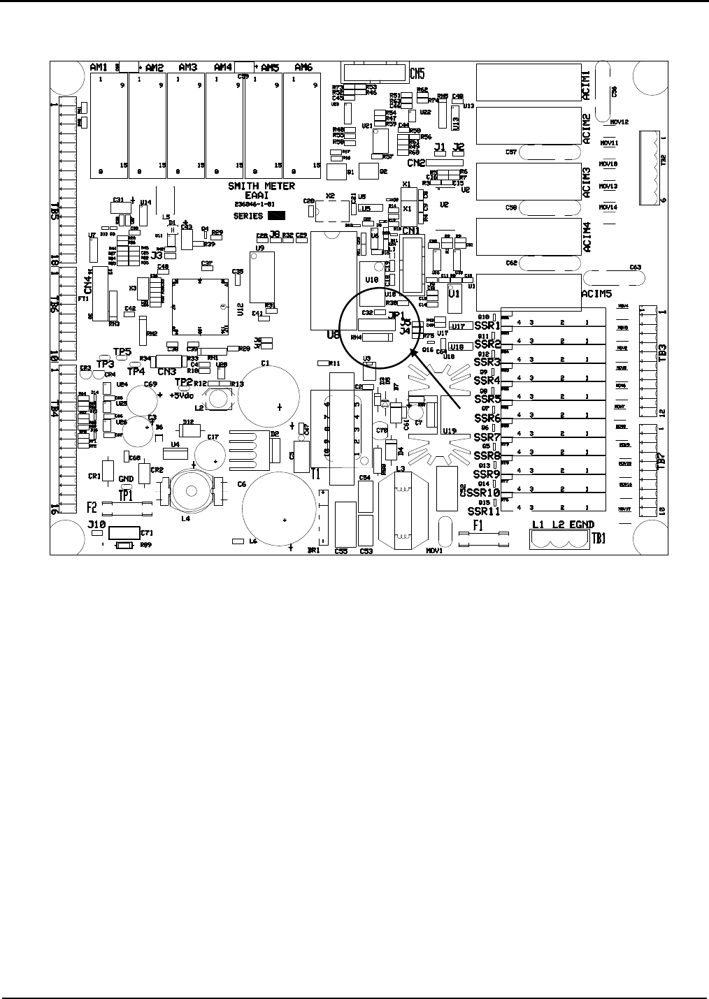
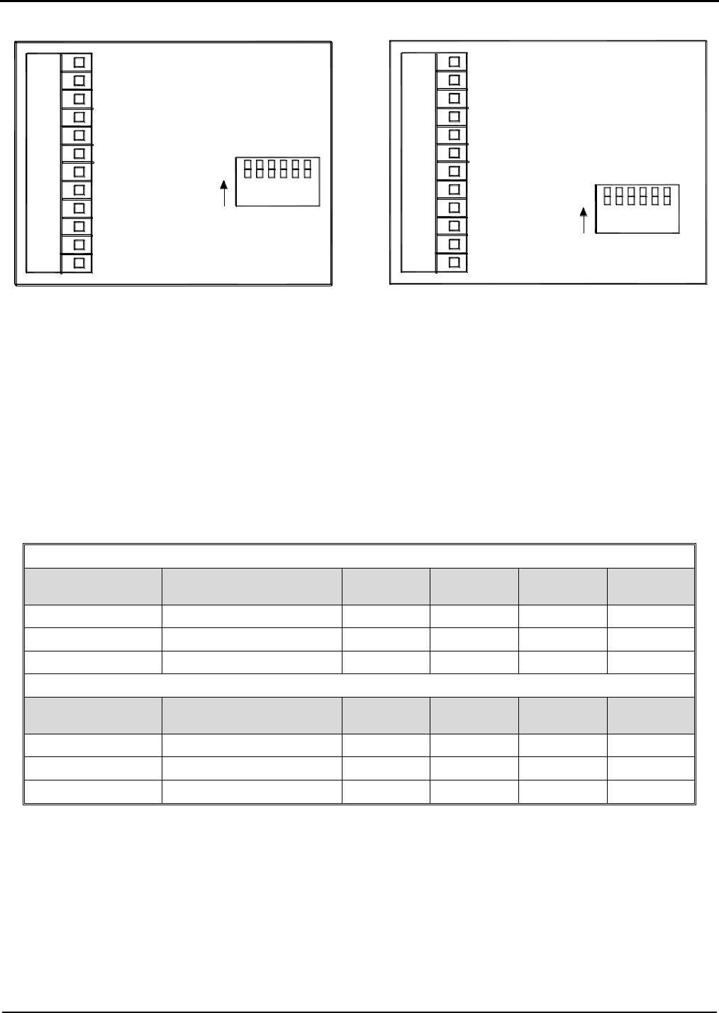
Figure 8. EAAI Layout
The user-configurable jumper on the EAAI board is indicated by a circle and arrow in the diagram above. See the
table on the following page for an explanation of analog module settings. This jumper has been configured for the
modules that were shipped with the unit. Changes should only be made if different modules are added or deleted.
Modules must be installed with inputs first, followed by outputs.
Ribbon Cable
Section IV – Diagrams
12 MN06140 Issue/Rev. 0.6 (8/15)
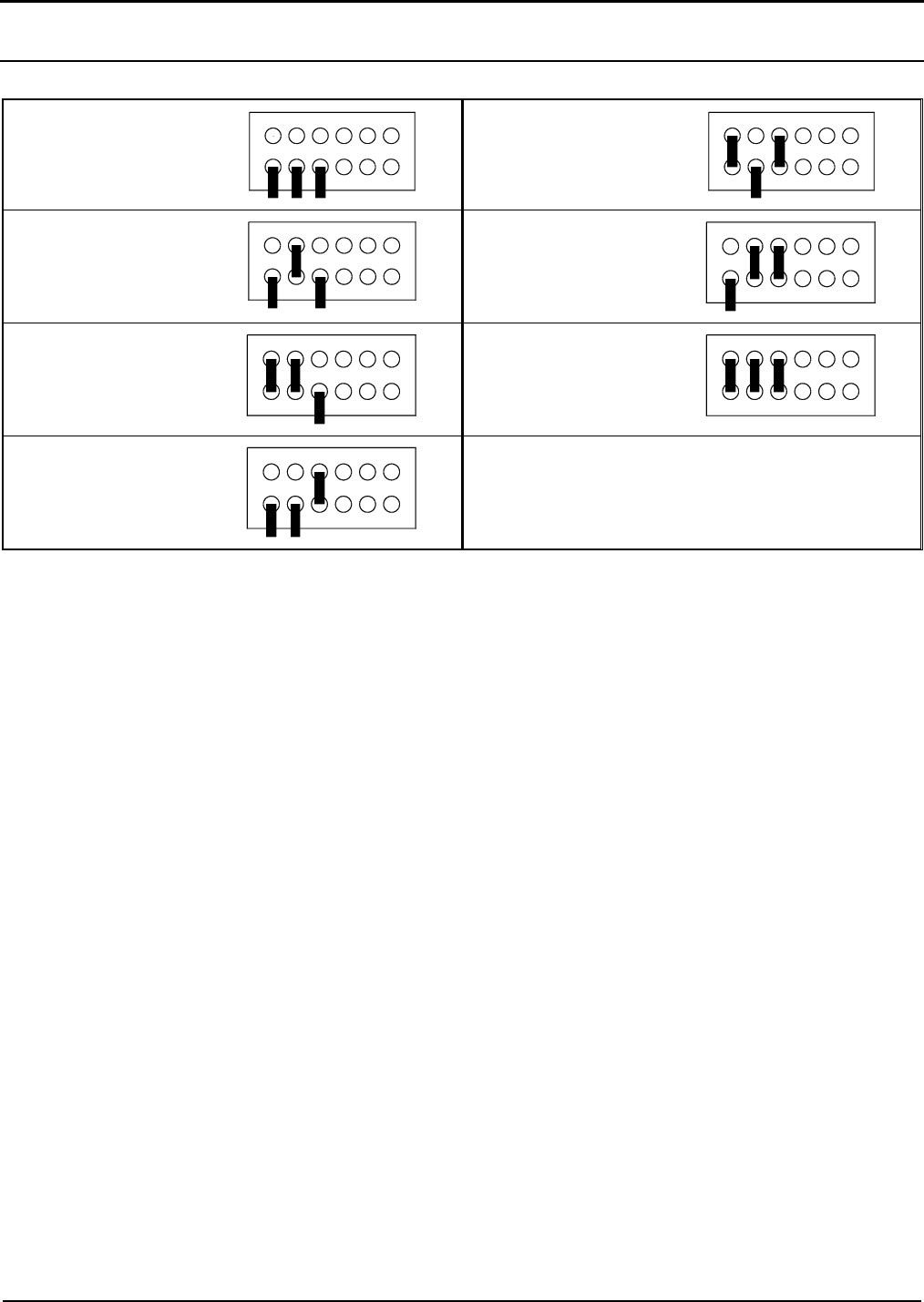
Analog Module Settings (JP1 on EAAI)
6 Inputs, 0 Outputs
2 Inputs, 4 Outputs
5 Inputs, 1 Output
1 Input, 5 Outputs
4 Inputs, 2 Outputs
0 Inputs, 6 Outputs
3 Inputs, 3 Outputs
Table 4. Analog Module Settings
Section IV – Diagrams
MN06140 Issue/Rev. 0.6 (8/15) 13
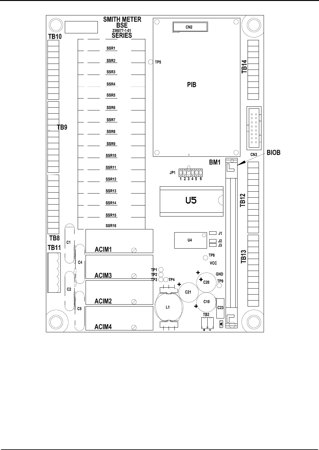
Figure 9. BSE Layout
Note: JP1 3 through 6 define the number of BIOB inputs. JP1 1 and 2 are not used.
Ribbon
Cable
Section IV – Diagrams
14 MN06140 Issue/Rev. 0.6 (8/15)
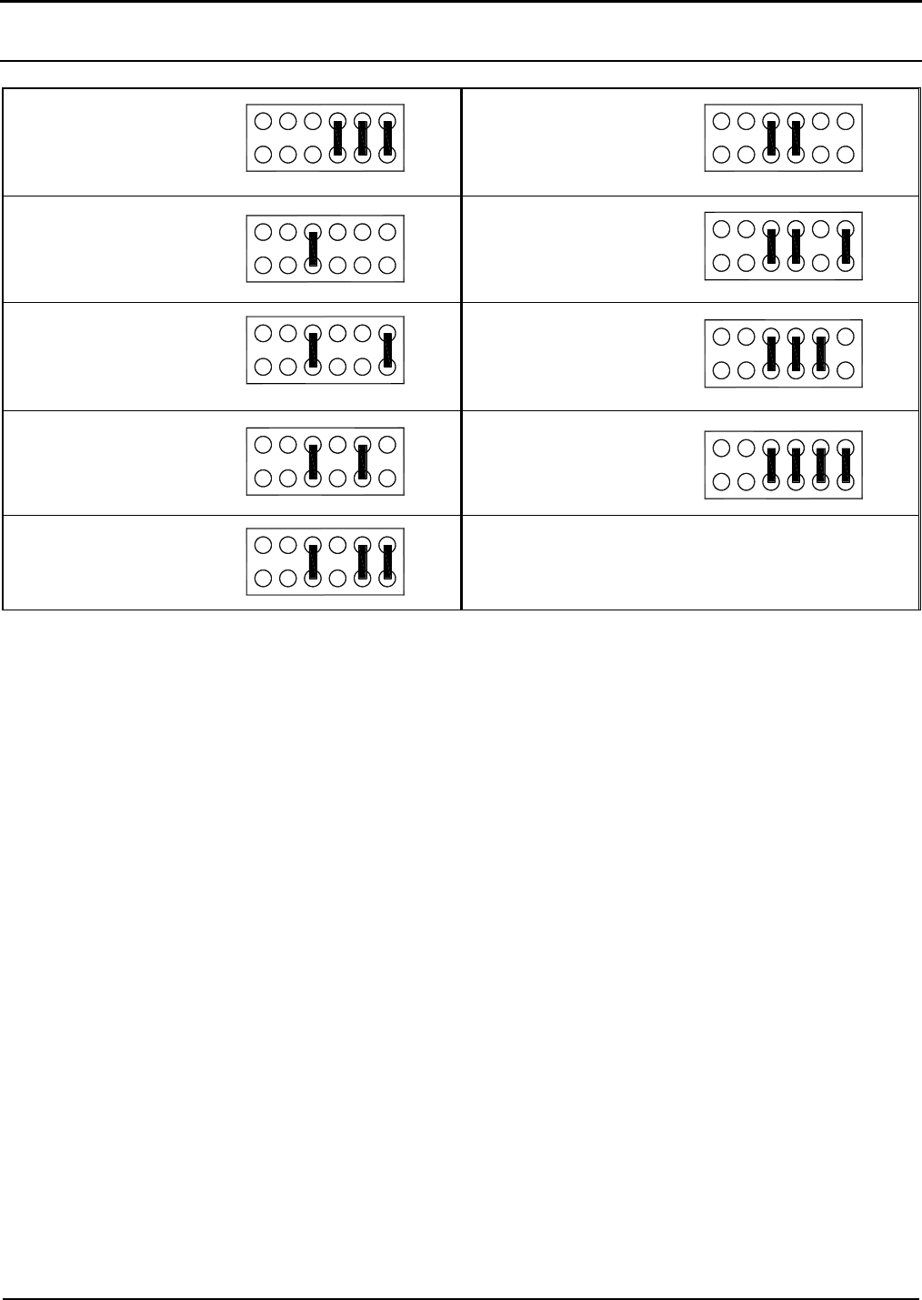
Bi-State DC Inputs and Output Jumper Settings (JP1 on the BSE)
8 Inputs, 0 Outputs
3 Inputs, 5 Outputs
7 Inputs, 1 Output
2 Input, 6 Outputs
6 Inputs, 2 Outputs
1 Inputs, 7 Outputs
5 Inputs, 3 Outputs
0 Inputs, 8 Outputs
4 Inputs, 4 Outputs
Table 5. Bi-State Inputs and Outputs
Section IV – Diagrams
MN06140 Issue/Rev. 0.6 (8/15) 15
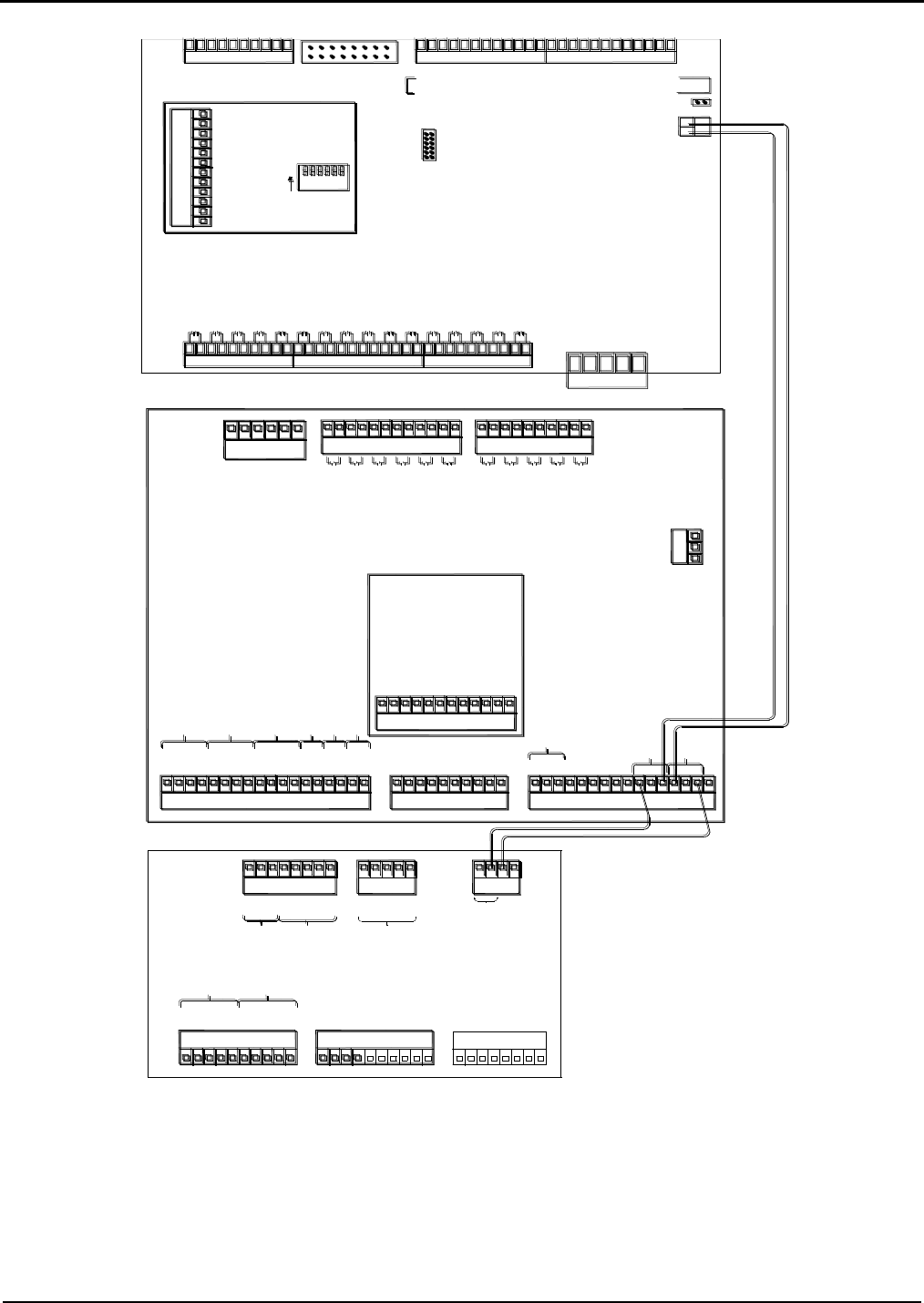
Figure 10. KDC/EAAI/PIB/BSE Boards (One Board Set)
Caution: Each board set should be handled individually and contains its own “unique” 24v DC power supply. All
external devices such as pulse transmitters, RTD’s, 4-20mA devices and communication wiring that interface with a
board set MUST be powered by the +24VDC supplied by that board set and all the grounds including shield wires
must be connected/isolated to that board set, including the associated +24VDC distribution board. A sharing of pow-
er supplies and grounding between board sets can cause ground loops leading to communication problems,
external device issues and instability of the DC power supply output from the EAAI board.
EAAI
PIB
TB5
TB2
TB6
TB4
TB3
TB7
TB1
1
8
10
9
7
6
5
4
3
2
13
18
17
16
15
14
11
12
3
7
10
9
8
5
6
4
1
2
3
14
16
15
12
13
11
7
10
9
8
5
6
4
1
2
3
5
6
4
1
2
3
12
11
7
10
9
8
5
6
4
1
2
3
7
10
9
8
5
6
4
1
2
1
2
3
+
-
+
-
+
-
+
-
-
+
-
+
Pulse In #1
Pulse In #2
Pulse In #4
Pulse In #3
Pulse In #6
Pulse In #5
3
12
11
7
10
9
8
5
6
4
1
2
RTD +
SIG +
SIG -
RTD -
SIG -
RTD -
RTD +
SIG +
RTD -
SIG -
RTD +
SIG +
SIG -
SIG +
SIG -
SIG +
SIG -
SIG +
AM #1
AM #2
AM #3
AM #4
AM #5
AM #6
PT1
FT1
FT2
FT4
FT3
FT8
FT7
FT6
FT5
FT9
FT10
TX
RX
Gnd
+
-
+
-
-
N.C.
+24 VDC
Out
DC
Gnd
In #4 DC
In #5 DC
In #6 DC
Com #4
232
L1
Gnd
L2
AC in Com
In #7 (AC)
In #8 (AC)
In #9 (AC)
In #10 (AC)
In #11 (AC)
Out #4 (AC)
Out #5 (AC)
Out #6 (AC)
Out #7 (AC)
Out #8 (AC)
Out #9 (AC)
Out #10 (AC)
Out #11 (AC)
Out #12 (AC)
Out #13 (AC)
Out #14 (AC)
Notice: Before returning EAAI board to factory for service
remove all analog modules, AC Input and Output Modules
and PIB Board. Reinstall all modules into their respective
locations on the EAAI replacement board.
WARNING: CMOS Circuitry. Use grounded facility when
handling.
+
Com #6
5
AC In Com
In #15 AC
In #14 AC
5
4
3
BIO Out #8
Com #8
BIO In #8
BIO Out #7
Com #7
BIO In #7
BIO Out #6
TB2
-
+
1
J6
2
12
TB13
9
11
10
7
8
6
Smith Meter
2
Out # 27 AC
10
In #13AC
In #12 AC
2
1
TB11
TB8
7
9
8
5
6
4
Out # 30 AC
Out # 29 AC
Out # 28 AC
9
12
1
2
3
11
10
Out # 26 AC
Out # 25 AC
Out # 24 AC
6
7
8
4
5
3
Out # 22 AC
Out # 23 AC
Out # 21 AC
BSE
6
Out # 17 AC
9
1
10
8
7
Out # 20 AC
Out # 19 AC
TB9
Out # 18 AC
4
5
3
TB10
1
2
Out # 16 AC
Out # 15 AC
Board
OFF = X2
On = X1
2
BIO In #6
BIO Out #5
Com #5
BIO In #5
BIO Out #4
Com #4
BIO In #4
BIO Out #3
Com #3
BIO In #3
BIO Out #2
Com #2
BIO In #2
BIO Out #1
Com #1
BIO In #1
6543
1
JP1
6
5
4
3
2
S1
4
11
2
4
3
12
1
10
9
8
6
7
5
1
3
2
TB12
Gnd
Gnd
FT8
FT7
FT6
FT5
FT4
FT3
FT2
FT1
1
8
Pulse In #10
-
Pulse In #11
Pulse In #12
-
+
+
-
12
11
10
9
Pulse In #9
Pulse In #8
Pulse In #7
PIB
ON
3
+
+
+
-
-
5
7
6
4
-
+
1
2
PT1
6
9
10
8
7
4
5
3
TB14
1
2
KDC
TB1
TB4
TB5
TB6
TB3
TB2
1
2
3
4
5
6
7
8
9
10
1
8
10
9
7
6
5
4
3
2
4
8
7
6
5
2
3
1
7
8
5
6
4
3
2
1
3
5
4
1
2
4
2
3
1
TX
RX
RTS
CTS
COM
TX +
TX -
RX +
RX -
COM
232
485
COM #1
+
-
+
-
+
-
+
-
N.C.
N.C.
In #1 DC
In #2 DC
In #3 DC
Pulse Out #1
Out #1 DC
-
+
Out #2 DC
-
+
Out #3 DC
+
-
Pulse Out #2
+
-
+24 VDC In
Gnd
Gnd
COM
RX -
RX +
TX -
TX +
COM #3
485
RX -
TX +
TX -
RX +
COM
COM
RX
TX
485
232
COM #2
Prewired at the factory
Section IV – Diagrams
16 MN06140 Issue/Rev. 0.6 (8/15)
Figure 11. PIB Boards (One Board Set)
Caution: Each board set should be handled individually and contains its own “unique” 24v DC power supply. All
external devices such as pulse transmitters, RTD’s, 4-20mA devices and communication wiring that interface with a
board set MUST be powered by the +24VDC supplied by that board set and all the grounds including shield wires
must be connected/isolated to that board set, including the associated +24VDC distribution block. A sharing of power
supplies and grounding between board sets can cause ground loops leading to communication problems, external
device issues and instability of the DC power supply output from the EAAI board.
The PIB boards provide the connectors for wiring the pulse inputs. Refer to the table on the following page to
determine what connectors to use for specific pulse inputs.
Pulse doubling: S1 on the PIBs is used for multiplying the meter inputs by two (X2). Refer to the following chart to
determine which position on S1 to use for each meter input.
S1 on EAAI PIB
6-Product Meters
5-Product Meters
4-Product
Meters
3-Product
Meters
2-Product
Meters
1-Product
Meter
Meter 1, S1-1
Meter 1, S1-1
Meter 1, S1-1
Meter 1, S1-1
Meter 1, S1-1
Meter 1, S1-1
Meter 2, S1-2
Meter 2, S1-2
Meter 2, S1-2
Meter 2, S1-2
Meter 2, S1-2
X
Meter 3, S1-3
Meter 3, S1-3
X
X
X
X
S1 on BSE PIB
6-Product Meters
5-Product Meters
4-Product
Meters
3-Product
Meters
2-Product
Meters
1-Product
Meter
Meter 4, S1-1
Meter 4, S1-1
Meter 3, S1-1
Meter 3, S1-3
X
X
Meter 5, S1-2
Meter 5, S1-2
Meter 4, S1-2
X
X
X
Meter 6, S1-3
X
X
X
X
X
Note: Switches 4, 5, and 6 on S1 (PIB) not used.
PIB Update
Date/Revision Functionality
4/04/2002 – Rev. 1 to Rev. 2 Expanded memory cells and switched to surface mount EPLD
8/29/2005 – Rev. 2 to Rev. 3 High speed prover output
Note: If AccuLoad III-X Rev. 10.12 or higher is being used and the reverse flow is implemented; PIB board Rev. 3 or above must be used.
EAAI PIB
+
-
+
-
+
-
+
-
-
+
-
+
Pulse In #1
Pulse In #2
Pulse In #4
Pulse In #3
Pulse In #6
Pulse In #5
3
12
11
7
10
9
8
5
6
4
1
2
PT1
Board
OFF = X2
On = X1
2 6543
S1
1
8
Pulse In #10
-
Pulse In #11
Pulse In #12
-
+
+
-
12
11
10
9
Pulse In #9
Pulse In #8
Pulse In #7
BSE PIB
ON
3
+
+
+
-
-
5
7
6
4
-
+
1
2
PT1
2
On = X1
OFF = X2
S1
5 63 4
ON
1
Board

Section IV – Diagrams
MN06140 Issue/Rev. 0.6 (8/15) 17
Pulse Inputs (One Board Set)
6-Product Meters
Input #1
Input #2
Input #3
Input #4
Input #5
Input #6
Single Pulse
Meter #1A
Meter #2A
Meter # 3A
Injector/Dens.
Injector/Dens.
Injector/Dens.
Dual Pulse
Meter #1A
Meter #1B
Meter # 3A
Meter #2A
Meter #2B
Meter # 3B
Dual/Integrity
N/A
N/A
N/A
N/A
N/A
N/A
Input #7
Input #8
Input #9
Input #10
Input #11
Input #12
Single Pulse
Meter #4A
Meter #5A
Meter #6A
Injector/Dens.
Injector/Dens.
Injector/Dens.
Dual Pulse
Meter #4A
Meter #4B
Meter #6A
Meter #5A
Meter #5B
Meter #6B
Dual/Integrity
N/A
N/A
N/A
N/A
N/A
N/A
5-Product Meters
Input #1
Input #2
Input #3
Input #4
Input #5
Input #6
Single Pulse
Meter #1A
Meter #2A
Meter # 3A
Injector/Dens.
Injector/Dens.
Injector/Dens.
Dual Pulse
Meter #1A
Meter #1B
Meter # 3A
Meter #2A
Meter #2B
Meter # 3B
Dual/Integrity
N/A
N/A
N/A
N/A
N/A
N/A
Input #7
Input #8
Input #9
Input #10
Input #11
Input #12
Single Pulse
Meter #4A
Meter #5A
Injector/Dens.
Injector/Dens.
Injector/Dens.
Injector/Dens.
Dual Pulse
Meter #4A
Meter #4B
Injector/Dens.
Meter #5A
Meter #5B
Injector/Dens.
Dual/Integrity
N/A
N/A
N/A
N/A
N/A
N/A
4-Product Meters
Input #1
Input #2
Input #3
Input #4
Input #5
Input #6
Single Pulse
Meter #1A
Meter #2A
Injector/Dens.
Injector/Dens.
Injector/Dens.
Injector/Dens.
Dual Pulse
Meter #1A
Meter #1B
Injector/Dens.
Meter #2A
Meter #2B
Injector/Dens.
Dual/Integrity
Meter #1A
Meter #1B
Meter #1A Bar
Meter #2A
Meter #2B
Meter #2A Bar
Input #7
Input #8
Input #9
Input #10
Input #11
Input #12
Single Pulse
Meter #3A
Meter #4A
Injector/Dens.
Injector/Dens.
Injector/Dens.
Injector/Dens.
Dual Pulse
Meter #3A
Meter #3B
Injector/Dens.
Meter #4A
Meter #4B
Injector/Dens.
Dual/Integrity
Meter #3A
Meter #3B
Meter #3A Bar
Meter #4A
Meter #4B
Meter #4A Bar
3-Product Meters
Input #1
Input #2
Input #3
Input #4
Input #5
Input #6
Single Pulse
Meter #1A
Meter #2A
Injector/Dens.
Injector/Dens.
Injector/Dens.
Injector/Dens.
Dual Pulse
Meter #1A
Meter #1B
Injector/Dens.
Meter #2A
Meter #2B
Injector/Dens.
Dual/Integrity
Meter #1A
Meter #1B
Meter #1A Bar
Meter #2A
Meter #2B
Meter #2A Bar
Input #7
Input #8
Input #9
Input #10
Input #11
Input #12
Single Pulse
Meter #3A
Injector
Injector/Dens.
Injector/Dens.
Injector/Dens.
Injector/Dens.
Dual Pulse
Meter #3A
Meter #3B
Injector/Dens.
Reserved
Reserved
Injector/Dens.
Dual/Integrity
Meter #3A
Meter #3B
Meter #3A Bar
Injector/Dens.
Injector/Dens.
Injector/Dens.
Section IV – Diagrams
18 MN06140 Issue/Rev. 0.6 (8/15)
2-Product Meters
Input #1
Input #2
Input #3
Input #4
Input #5
Input #6
Single Pulse
Meter #1A
Meter #2A
Injector/Dens.
Injector/Dens.
Injector/Dens.
Injector/Dens.
Dual Pulse
Meter #1A
Meter #1B
Injector/Dens.
Meter #2A
Meter #2B
Injector/Dens.
Dual/Integrity
Meter #1A
Meter #1B
Meter #1A Bar
Meter #2A
Meter #2B
Meter #2A Bar
Input #7
Input #8
Input #9
Input #10
Input #11
Input #12
Single Pulse
Injector
Injector
Injector/Dens.
Injector/Dens.
Injector/Dens.
Injector/Dens.
Dual Pulse
Injector
Injector
Injector/Dens.
Injector/Dens.
Injector/Dens.
Injector/Dens.
Dual/Integrity
Injector
Injector
Injector/Dens.
Injector/Dens.
Injector/Dens.
Injector/Dens.
1-Product Meter
Input #1
Input #2
Input #3
Input #4
Input #5
Input #6
Single Pulse
Meter #1A
Reserved
Injector/Dens.
Injector/Dens.
Injector/Dens.
Injector/Dens.
Dual Pulse
Meter #1A
Meter #1B
Reserved
Injector/Dens.
Injector/Dens.
Injector/Dens.
Dual/Integrity
Meter #1A
Meter #1B
Meter #1A Bar
Injector/Dens.
Injector/Dens.
Injector/Dens.
Input #7
Input #8
Input #9
Input #10
Input #11
Input #12
Single Pulse
Injector
Injector
Injector/Dens.
Injector/Dens.
Injector/Dens.
Injector/Dens.
Dual Pulse
Injector
Injector
Injector/Dens.
Injector/Dens.
Injector/Dens.
Injector/Dens.
Dual/Integrity
Injector
Injector
Injector/Dens.
Injector/Dens.
Injector/Dens.
Injector/Dens.
Table 6. Pulse Inputs
Note: When using dual pulse and not the A Bar inputs for transmitter security, the pulse inputs for the A Bar assignment will be not used.
Caution: Each board set should be handled individually and contains its own “unique” 24v DC power supply. All
external devices such as pulse transmitters, RTD’s, 4-20mA devices and communication wiring that interface with a
board set MUST be powered by the +24VDC supplied by that board set and all the grounds including shield wires
must be connected/isolated to that board set, including the associated +24VDC distribution block. A sharing of power
supplies and grounding between board sets can cause ground loops leading to communication problems, external
device issues and instability of the DC power supply output from the EAAI board.
Dual Pulse Inputs for Rev. 10.07 and Above Firmware (With Flow Controlled Additive)
5 Product Meters with 1 Flow Controlled Additive
Input #1
Input #2
Input #3
Input #4
Input #5
Input #6
Dual Pulse
Meter #1A
Meter #1B
Meter #3A
Meter #2A
Meter #2B
Meter #3B
Dual/Integrity
NA
NA
NA
NA
NA
NA
Input #7
Input #8
Input #9
Input #10
Input #11
Input #12
Dual Pulse
Meter #4A
Meter #4B
FC Inj #1A
Meter #5A
Meter #5B
FC Inj #1B
Dual/Integrity
NA
NA
NA
NA
NA
NA
4 Product Meters with 2 Flow Controlled Additive
Input #1
Input #2
Input #3
Input #4
Input #5
Input #6
Dual Pulse
Meter #1A
Meter #1B
Meter #3A
Meter #2A
Meter #2B
Meter #3B
Dual/Integrity
NA
NA
NA
NA
NA
NA
Input #7
Input #8
Input #9
Input #10
Input #11
Input #12
Dual Pulse
Meter #4A
Meter #4B
FC Inj #2A
FC Inj #1A
FC Inj #1B
FC Inj #2B
Dual/Integrity
NA
NA
NA
NA
NA
NA
Section IV – Diagrams
MN06140 Issue/Rev. 0.6 (8/15) 19
4 Product Meters with 1 Flow Controlled Additive
Input #1
Input #2
Input #3
Input #4
Input #5
Input #6
Dual Pulse
Meter #1A
Meter #1B
Meter #3A
Meter #2A
Meter #2B
Meter #3B
Dual/Integrity
NA
NA
NA
NA
NA
NA
Input #7
Input #8
Input #9
Input #10
Input #11
Input #12
Dual Pulse
Meter #4A
Meter #4B
Injector/Dens
FC Inj #1A
FC Inj #1B
Injector/Dens
Dual/Integrity
NA
NA
NA
NA
NA
NA
3 Product Meters with 3 Flow Controlled Additive
Input #1
Input #2
Input #3
Input #4
Input #5
Input #6
Dual Pulse
Meter #1A
Meter #1B
Meter #3A
Meter #2A
Meter #2B
Meter #3B
Dual/Integrity
NA
NA
NA
NA
NA
NA
Input #7
Input #8
Input #9
Input #10
Input #11
Input #12
Dual Pulse
FC Inj #1A
FC Inj #1B
FC Inj #3A
FC Inj #2A
FC Inj #2B
FC Inj #3B
Dual/Integrity
NA
NA
NA
NA
NA
NA
3 Product Meters with 2 Flow Controlled Additive
Input #1
Input #2
Input #3
Input #4
Input #5
Input #6
Dual Pulse
Meter #1A
Meter #1B
Meter #3A
Meter #2A
Meter #2B
Meter #3B
Dual/Integrity
NA
NA
NA
NA
NA
NA
Input #7
Input #8
Input #9
Input #10
Input #11
Input #12
Dual Pulse
FC Inj #1A
FC Inj #1B
Injector/Dens
FC Inj #2A
FC Inj #2B
Injector/Dens
Dual/Integrity
NA
NA
NA
NA
NA
NA
3 Product Meters with 1 Flow Controlled Additive
Input #1
Input #2
Input #3
Input #4
Input #5
Input #6
Dual Pulse
Meter #1A
Meter #1B
Injector/Dens
Meter #2A
Meter #2B
Injector/Dens
Dual/Integrity
Meter #1A
Meter #1B
Meter #1 Bar
Meter #2A
Meter #2B
Meter #2 Bar
Input #7
Input #8
Input #9
Input #10
Input #11
Input #12
Dual Pulse
Meter #3A
Meter #3B
Injector/Dens
FC Inj #1A
FC Inj #1B
Injector/Dens
Dual/Integrity
Meter #3A
Meter #3B
Meter #3 Bar
FC Inj #1A
FC Inj #1B
FC Inj #1 Bar
2 Product Meters with 4 Flow Controlled Additive
Input #1
Input #2
Input #3
Input #4
Input #5
Input #6
Dual Pulse
Meter #1A
Meter #1B
FC Inj #1A
Meter #2A
Meter #2B
FC Inj #1B
Dual/Integrity
NA
NA
NA
NA
NA
NA
Input #7
Input #8
Input #9
Input #10
Input #11
Input #12
Dual Pulse
FC Inj #2A
FC Inj #2B
FC Inj #4A
FC Inj #3A
FC Inj #3B
FC Inj #4B
Dual/Integrity
NA
NA
NA
NA
NA
NA

Section IV – Diagrams
20 MN06140 Issue/Rev. 0.6 (8/15)
2 Product Meters with 3 Flow Controlled Additive
Input #1
Input #2
Input #3
Input #4
Input #5
Input #6
Dual Pulse
Meter #1A
Meter #1B
FC Inj #1A
Meter #2A
Meter #2B
FC Inj #1B
Dual/Integrity
NA
NA
NA
NA
NA
NA
Input #7
Input #8
Input #9
Input #10
Input #11
Input #12
Dual Pulse
FC Inj #2A
FC Inj #2B
Injector/Dens
FC Inj #3A
FC Inj #3B
Injector/Dens
Dual/Integrity
NA
NA
NA
NA
NA
NA
2 Product Meters with 2 Flow Controlled Additive
Input #1
Input #2
Input #3
Input #4
Input #5
Input #6
Dual Pulse
Meter #1A
Meter #1B
Injector/Dens
Meter #2A
Meter #2B
Injector/Dens
Dual/Integrity
Meter #1A
Meter #1B
Meter #1 Bar
Meter #2A
Meter #2B
Meter #2 Bar
Input #7
Input #8
Input #9
Input #10
Input #11
Input #12
Dual Pulse
FC Inj #1A
FC Inj #1B
Injector/Dens
FC Inj #2A
FC Inj #2B
Injector/Dens
Dual/Integrity
FC Inj #1A
FC Inj #1B
FC Inj #1 Bar
FC Inj #2A
FC Inj #2B
FC Inj #2 Bar
2 Product Meters with 1 Flow Controlled Additive
Input #1
Input #2
Input #3
Input #4
Input #5
Input #6
Dual Pulse
Meter #1A
Meter #1B
Injector/Dens
Meter #2A
Meter #2B
Injector/Dens
Dual/Integrity
Meter #1A
Meter #1B
Meter #1 Bar
Meter #2A
Meter #2B
Meter #2 Bar
Input #7
Input #8
Input #9
Input #10
Input #11
Input #12
Dual Pulse
FC Inj #1A
FC Inj #1B
Injector/Dens
Reserved
Reserved
Injector/Dens
Dual/Integrity
FC Inj #1A
FC Inj #1B
FC Inj #1 Bar
Injector/Dens
Injector/Dens
Injector/Dens
1 Product Meters with 4 Flow Controlled Additive
Input #1
Input #2
Input #3
Input #4
Input #5
Input #6
Dual Pulse
Meter #1A
Meter #1B
FC Inj #2A
FC Inj #1A
FC Inj 1 B
PC Inj #2B
Dual/Integrity
NA
NA
NA
NA
NA
NA
Input #7
Input #8
Input #9
Input #10
Input #11
Input #12
Dual Pulse
FC Inj #3A
PC Inj #3B
Injector/Dens
FC Inj #4A
FC Inj #4B
Injector/Dens
Dual/Integrity
NA
NA
NA
NA
NA
NA
1 Product Meters with 3 Flow Controlled Additive
Input #1
Input #2
Input #3
Input #4
Input #5
Input #6
Dual Pulse
Meter #1A
Meter #1B
Injector/Dens
FC Inj #1A
FC Inj 1 B
Injector/Dens
Dual/Integrity
Meter #1A
Meter #1B
Meter #1 Bar
FC Inj #1A
FC Inj 1 B
FC Inj # 1 Bar
Input #7
Input #8
Input #9
Input #10
Input #11
Input #12
Dual Pulse
FC Inj #2A
PC Inj #2B
Injector/Dens
FC Inj #3A
FC Inj #3B
Injector/Dens
Dual/Integrity
FC Inj #2A
PC Inj #2B
PC Inj #2 Bar
FC Inj #3A
FC Inj #3B
FC Inj # 3 Bar

Section IV – Diagrams
MN06140 Issue/Rev. 0.6 (8/15) 21
1 Product Meters with 2 Flow Controlled Additive
Input #1
Input #2
Input #3
Input #4
Input #5
Input #6
Dual Pulse
Meter #1A
Meter #1B
Injector/Dens
FC Inj #1A
FC Inj 1 B
Injector/Dens
Dual/Integrity
Meter #1A
Meter #1B
Meter #1 Bar
FC Inj A
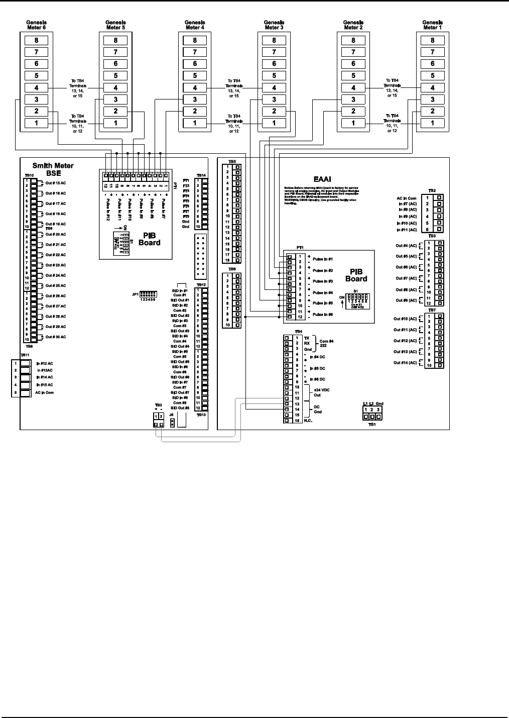
FC Inj 1 B
FC Inj Bar
Input #7
Input #8
Input #9
Input #10
Input #11
Input #12
Dual Pulse
FC Inj #2A
PC Inj #2B
Injector/Dens
Reserved
Reserved
Injector/Dens
Dual/Integrity
FC Inj #2A
PC Inj #2B
PC Inj #2 Bar
Injector/Dens
Injector/Dens
Injector/Dens
1 Product Meters with 1 Flow Controlled Additive
Input #1
Input #2
Input #3
Input #4
Input #5
Input #6
Dual Pulse
Meter #1A
Meter #1B
Injector/Dens
FC Inj A
FC Inj 1 B
Injector/Dens
Dual/Integrity
Meter #1A
Meter #1B
Meter #1 Bar
FC Inj A
FC Inj 1 B
FC Inj Bar
Input #7
Input #8
Input #9
Input #10
Input #11
Input #12
Dual Pulse
Injector
Injector
Injector/Dens
Injector/Dens
Injector/Dens
Injector/Dens
Dual/Integrity
Injector
Injector
Injector/Dens
Injector/Dens
Injector/Dens
Injector/Dens
Table 7. Dual Pulse Inputs
Section IV – Diagrams
22 MN06140 Issue/Rev. 0.6 (8/15)
Figure 12. MMI Wiring Diagram
KDC
TB1
TB4
TB5
TB6
TB3
TB2
1
2
3
4
5
6
7
8
9
10
1
8
10
9
7
6
5
4
3
2
4
8
7
6
5
2
3
1
7
8
5
6
4
3
2
1
3
5
4
1
2
4
2
3
1
TX
RX
RTS
CTS
COM
TX +
TX -
RX +
RX -
COM
232
485
COM #1
+
-
+
-
+
-
+
-
N.C.
N.C.
In #1 DC
In #2 DC
In #3 DC
Pulse Out #1
Out #1 DC
-
+
Out #2 DC
-
+
Out #3 DC
+
-
Pulse Out #2
+
-
+24 VDC In
Gnd
Gnd
COM
RX -
RX +
TX -
TX +
COM #3
485
RX -
TX +
TX -
RX +
COM
COM
RX
TX
485
232
COM #2
Stop Switch
Normally
Open
Normally
Closed
Red
IndicatorIndicator
Green
L1
NN
L1
From KDC
In FCM
Communications to
FCM
Power
Keypad
Back Side of MMI Door
Section IV – Diagrams
MN06140 Issue/Rev. 0.6 (8/15) 23
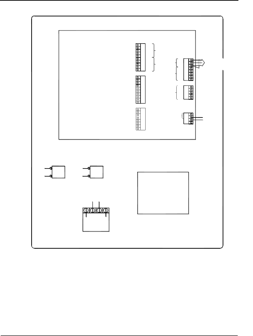
Figure 13. Wiring Diagram, Prime 4 Meter Single Pulse (One Board Set)
Caution: For clarity, shields not shown. Connect shields to Terminals 3, 13, 14, or 15 of Terminal Block 4.
Note: Wiring between transmitter and AccuLoad should be done using a shielded cable per each transmitter. If selected cable utilizes twisted
pairs, do not run more than one signal in a twisted pair.
Caution: Each board set should be handled individually and contains its own “unique” 24v DC power supply. All
external devices such as pulse transmitters, RTD’s, 4-20mA devices and communication wiring that interface with a
board set MUST be powered by the +24VDC supplied by that board set and all the grounds including shield wires
must be connected/isolated to that board set, including the associated +24VDC distribution block. A sharing of power
supplies and grounding between board sets can cause ground loops leading to communication problems, external
device issues and instability of the DC power supply output from the EAAI board.
Note: The 24-volt power for the transmitters can be wired through the terminal block located in the bottom of the cabinet, as shown in Figure 5.
Prime 4 Wire Codes:
Black: Common
Red: Input Power
White: Signal A Output
Yellow: Signal B Output
Section IV – Diagrams
24 MN06140 Issue/Rev. 0.6 (8/15)
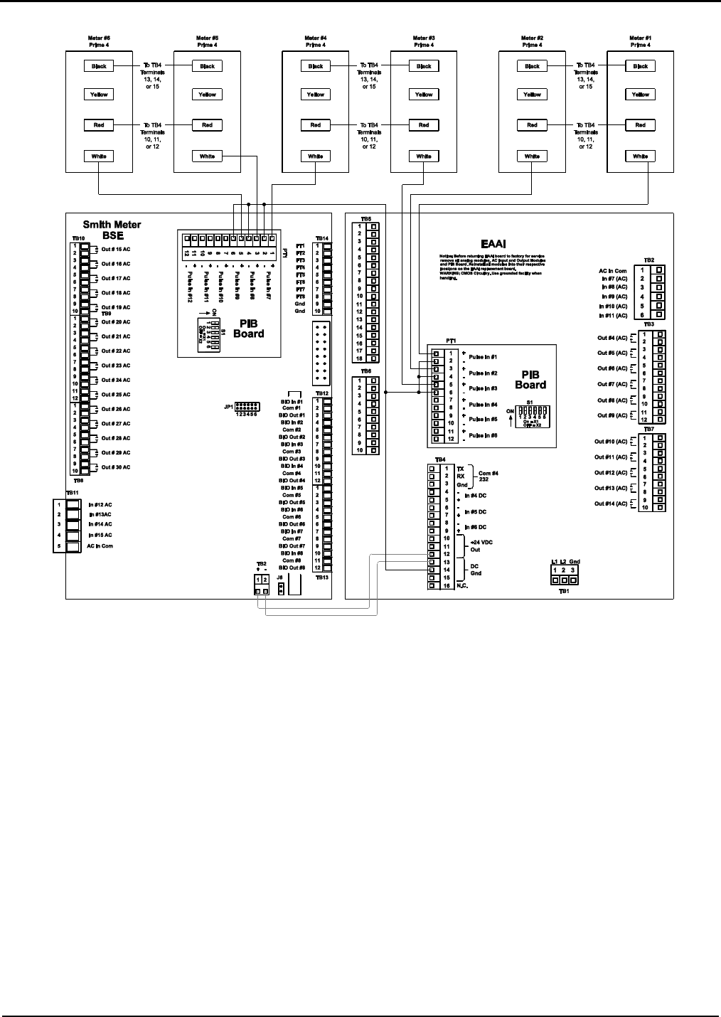
Figure 14. Wiring Diagram, Prime 4 Meters Dual Pulse (One Board Set)
Note: Drawing is shown with dual meters and each meter being shown wired as a dual pulse input. When not using the dual pulse input,
see figure 13.
Note: The 24-volt power for the transmitters can be wired through the terminal block located in the bottom of the cabinet, as shown in Figure 5.
Caution: For clarity, shields not shown. Connect shields to Terminals 3, 13, 14, or 15 of Terminal Block 4.
Note: Wiring between transmitter and AccuLoad should be done using a shielded cable per each transmitter. If selected cable utilizes twisted
pairs, do not run more than one signal in a twisted pair.
Caution: Each board set should be handled individually and contains its own “unique” 24v DC power supply. All
external devices such as pulse transmitters, RTD’s, 4-20mA devices and communication wiring that interface with a
board set MUST be powered by the +24VDC supplied by that board set and all the grounds including shield wires
must be connected/isolated to that board set, including the associated +24VDC distribution block. A sharing of power
supplies and grounding between board sets can cause ground loops leading to communication problems, external
device issues and instability of the DC power supply output from the EAAI board.
Prime 4 Wire Codes:
Black: Common
Red: Input Power
White: Signal A Output
Yellow: Signal B Output
Section IV – Diagrams
MN06140 Issue/Rev. 0.6 (8/15) 25
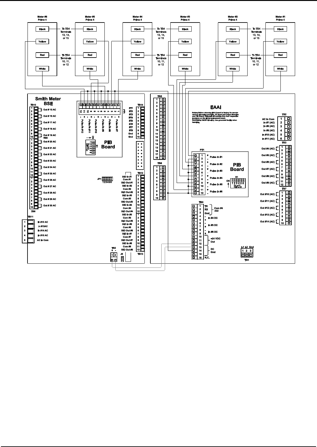
Figure 15. Wiring Diagram, Genesis Meter Single Pulse
Caution: For clarity, shields not shown. Connect shields to Terminals 3, 13, 14, or 15 of Terminal Block 4.
Note: Wiring between transmitter and AccuLoad should be done using a shielded cable per each transmitter. If selected cable utilizes twisted
pairs, do not run more than one signal in a twisted pair.
Genesis Terminal Connections:
1: Input Power
2: Signal A Output
3: Signal B Output
4: Electronics Ground
5: Not used
6: Not used
7: Not used
8: Not used
Caution: Each board set should be handled individually and contains
its own “unique” 24v DC power supply. All external devices such as
pulse transmitters, RTD’s, 4-20mA devices and communication wiring
that interface with a board set MUST be powered by the +24VDC
supplied by that board set and all the grounds including shield wires
must be connected/isolated to that board set, including the associated
+24VDC distribution block. A sharing of power supplies and grounding
between board sets can cause ground loops leading to communication
problems, external device issues and instability of the DC power supply
output from the EAAI board.
Section IV – Diagrams
26 MN06140 Issue/Rev. 0.6 (8/15)
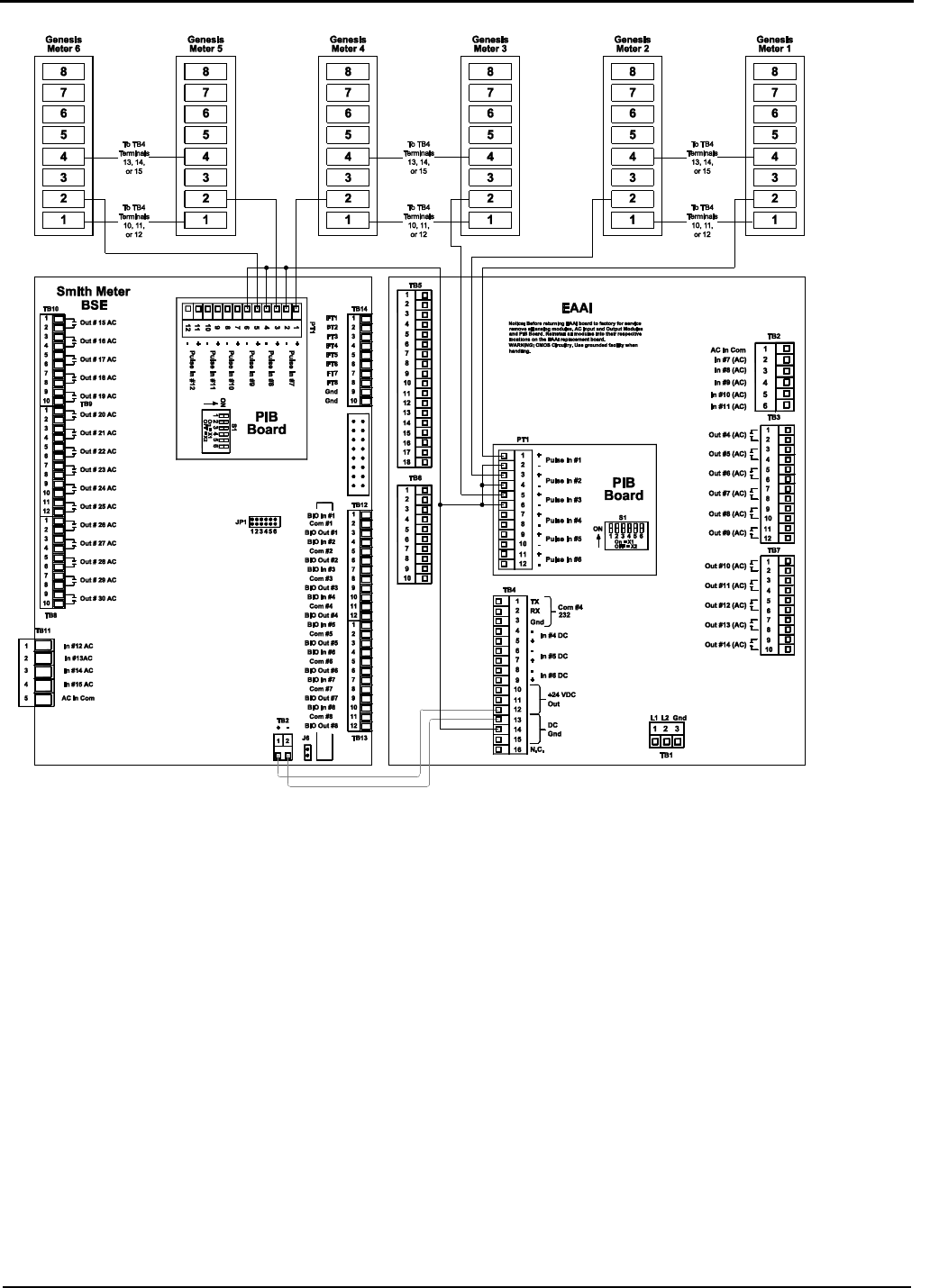
Figure 16. Wiring Diagram, Genesis Meter Dual Pulse
Caution: For clarity, shields not shown. Connect shields to Terminals 3, 13, 14, or 15 of Terminal Block 4.
Note: Wiring between transmitter and AccuLoad should be done using a shielded cable per each transmitter. If selected cable utilizes twisted
pairs, do not run more than one signal in a twisted pair.
Genesis Terminal Connections:
1: Input Power
2: Signal A Output
3: Signal B Output
4: Electronics Ground
5: Not used
6: Not used
7: Not used
8: Not used
Caution: Each board set should be handled individually and contains its
own “unique” 24v DC power supply. All external devices such as pulse
transmitters, RTD’s, 4-20mA devices and communication wiring that
interface with a board set MUST be powered by the +24VDC supplied
by that board set and all the grounds including shield wires must be
connected/isolated to that board set, including the associated +24VDC
distribution block. A sharing of power supplies and grounding between
board sets can cause ground loops leading to communication problems,
external device issues and instability of the DC power supply output from
the EAAI board.
Section IV – Diagrams
MN06140 Issue/Rev. 0.6 (8/15) 27
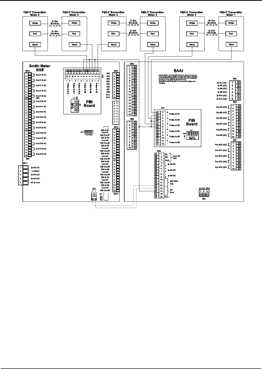
Figure 17. Wiring Diagram, PEX-P Transmitter Single Pulse (One Board Set)
Caution: For clarity, shields not shown. Connect shields to Terminals 3, 13, 14, or 15 of Terminal Block 4.
Note: Wiring between transmitter and AccuLoad should be done using a shielded cable per each transmitter. If selected cable utilizes twisted
pairs, do not run more than one signal in a twisted pair.
Caution: Each board set should be handled individually and contains its own “unique” 24v DC power supply. All
external devices such as pulse transmitters, RTD’s, 4-20mA devices and communication wiring that interface with a
board set MUST be powered by the +24VDC supplied by that board set and all the grounds including shield wires
must be connected/isolated to that board set, including the associated +24VDC distribution block. A sharing of power
supplies and grounding between board sets can cause ground loops leading to communication problems, external
device issues and instability of the DC power supply output from the EAAI board.
Note: The 24-volt power for the transmitters can be wired through the terminal block located in the bottom of the cabinet, as shown in Figure 5.
PEXP Wire Codes:
Black: Signal Output
Red: Input Power
White: Common
Section IV – Diagrams
28 MN06140 Issue/Rev. 0.6 (8/15)
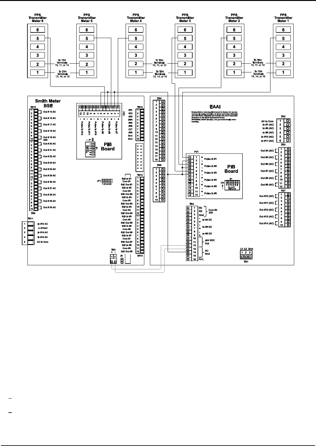
Figure 18. Wiring Diagram, PPS Transmitters Single Pulse (One Board Set)
Caution: For clarity, shields not shown. Connect shields to Terminals 3, 13, 14, or 15 of Terminal Block 4.
Note: Wiring between transmitter and AccuLoad should be done using a shielded cable per each transmitter. If selected cable utilizes twisted
pairs, do not run more than one signal in a twisted pair.
Caution: Each board set should be handled individually and contains its own “unique” 24v DC power supply. All
external devices such as pulse transmitters, RTD’s, 4-20mA devices and communication wiring that interface with a
board set MUST be powered by the +24VDC supplied by that board set and all the grounds including shield wires
must be connected/isolated to that board set, including the associated +24VDC distribution block. A sharing of power
supplies and grounding between board sets can cause ground loops leading to communication problems, external device
issues and instability of the DC power supply output from the EAAI board.
Note: The 24-volt power for the transmitters can be wired through the terminal block located in the bottom of the cabinet, as shown in Figure 5.
PPST Terminal Connections
1: Common
2: Input Power
3: Signal B Output
4: B Output
5: Signal A Output
6: A A Output
Section IV – Diagrams
MN06140 Issue/Rev. 0.6 (8/15) 29
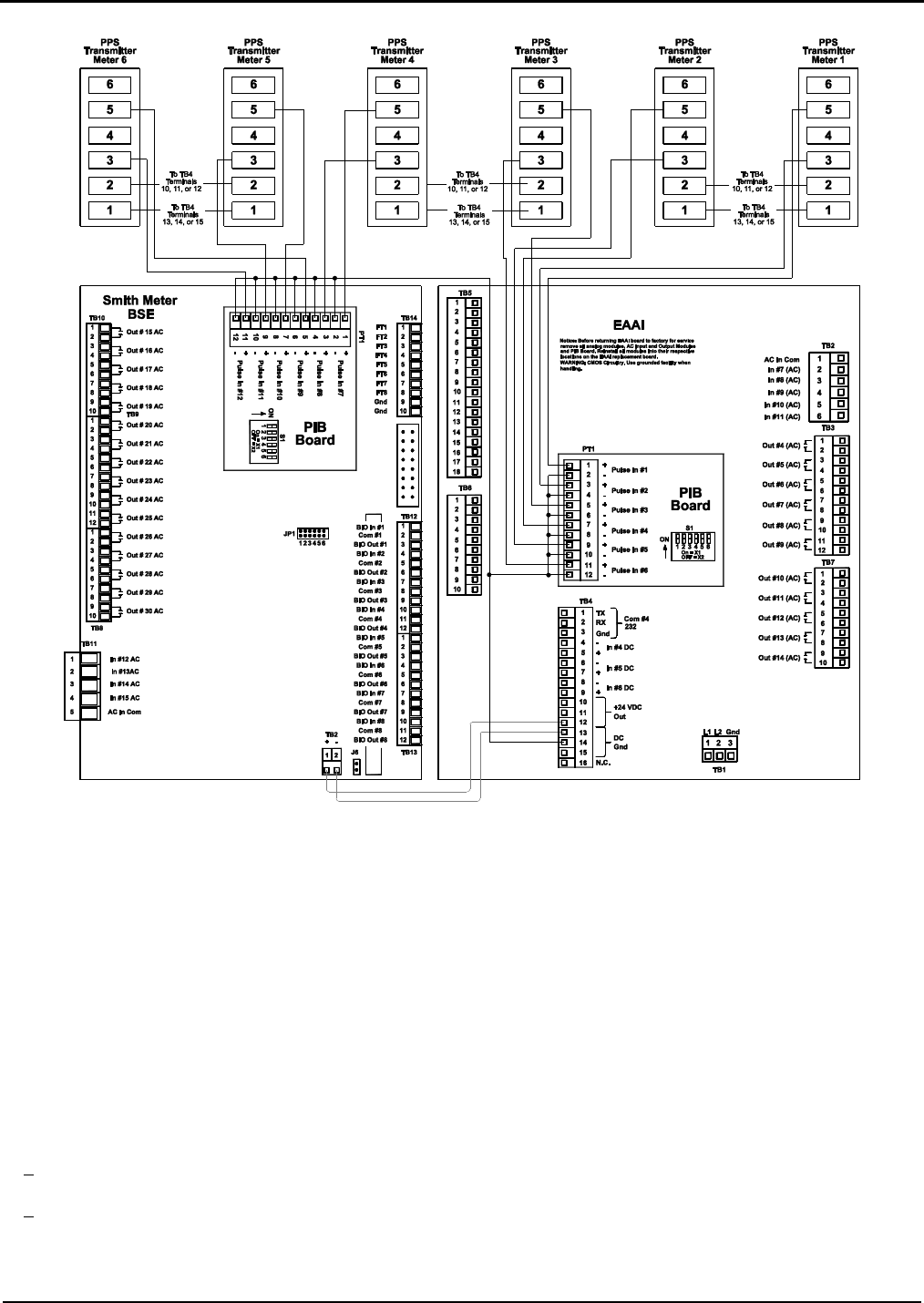
Figure 19. Wiring Diagram, PPS Dual Pulse Transmitter (One Board Set)
Caution: For clarity, shields not shown. Connect shields to Terminals 3, 13, 14, or 15 of Terminal Block 4.
Note: Wiring between transmitter and AccuLoad should be done using a shielded cable per each transmitter. If selected cable utilizes
twisted pairs, do not run more than one signal in a twisted pair.
Caution: Each board set should be handled individually and contains its own “unique” 24v DC power supply. All
external devices such as pulse transmitters, RTD’s, 4-20mA devices and communication wiring that interface with a
board set MUST be powered by the +24VDC supplied by that board set and all the grounds including shield wires
must be connected/isolated to that board set, including the associated +24VDC distribution block. A sharing of power
supplies and grounding between board sets can cause ground loops leading to communication problems, external
device issues and instability of the DC power supply output from the EAAI board.
Note: The 24-volt power for the transmitters can be wired through the terminal block located in the bottom of the cabinet, as shown in Figure 5.
PPST Terminal Connections
1: Common
2: Input Power
3: Signal B Output
4: B Output
5: Signal A Output
6: A Output
Section IV – Diagrams
30 MN06140 Issue/Rev. 0.6 (8/15)
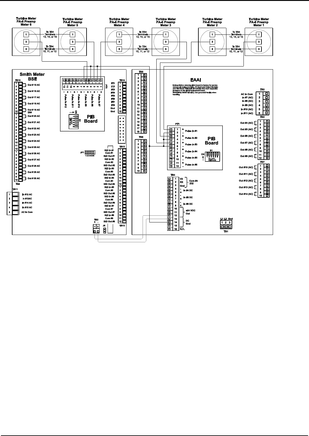
Figure 20. Wiring Diagram, Turbine Meters with PA-6 Pre-amps Single Pulse (One Board Set)
Caution: For clarity, shields not shown. Connect shields to Terminals 3, 13, 14, or 15 of Terminal Block 4.
Note: Wiring between transmitter and AccuLoad should be done using a shielded cable per each transmitter. If selected cable utilizes twisted
pairs, do not run more than one signal in a twisted pair.
Caution: Each board set should be handled individually and contains its own “unique” 24v DC power supply. All
external devices such as pulse transmitters, RTD’s, 4-20mA devices and communication wiring that interface with a
board set MUST be powered by the +24VDC supplied by that board set and all the grounds including shield wires
must be connected/isolated to that board set, including the associated +24VDC distribution block. A sharing of power
supplies and grounding between board sets can cause ground loops leading to communication problems, external
device issues and instability of the DC power supply output from the EAAI board.
Note: The 24-volt power for the transmitters can be wired through the terminal block located in the bottom of the cabinet, as shown in Figure 5.
PA-6 Terminal Connections
1: Common
3: Signal Output
5: Input Power
Section IV – Diagrams
MN06140 Issue/Rev. 0.6 (8/15) 31
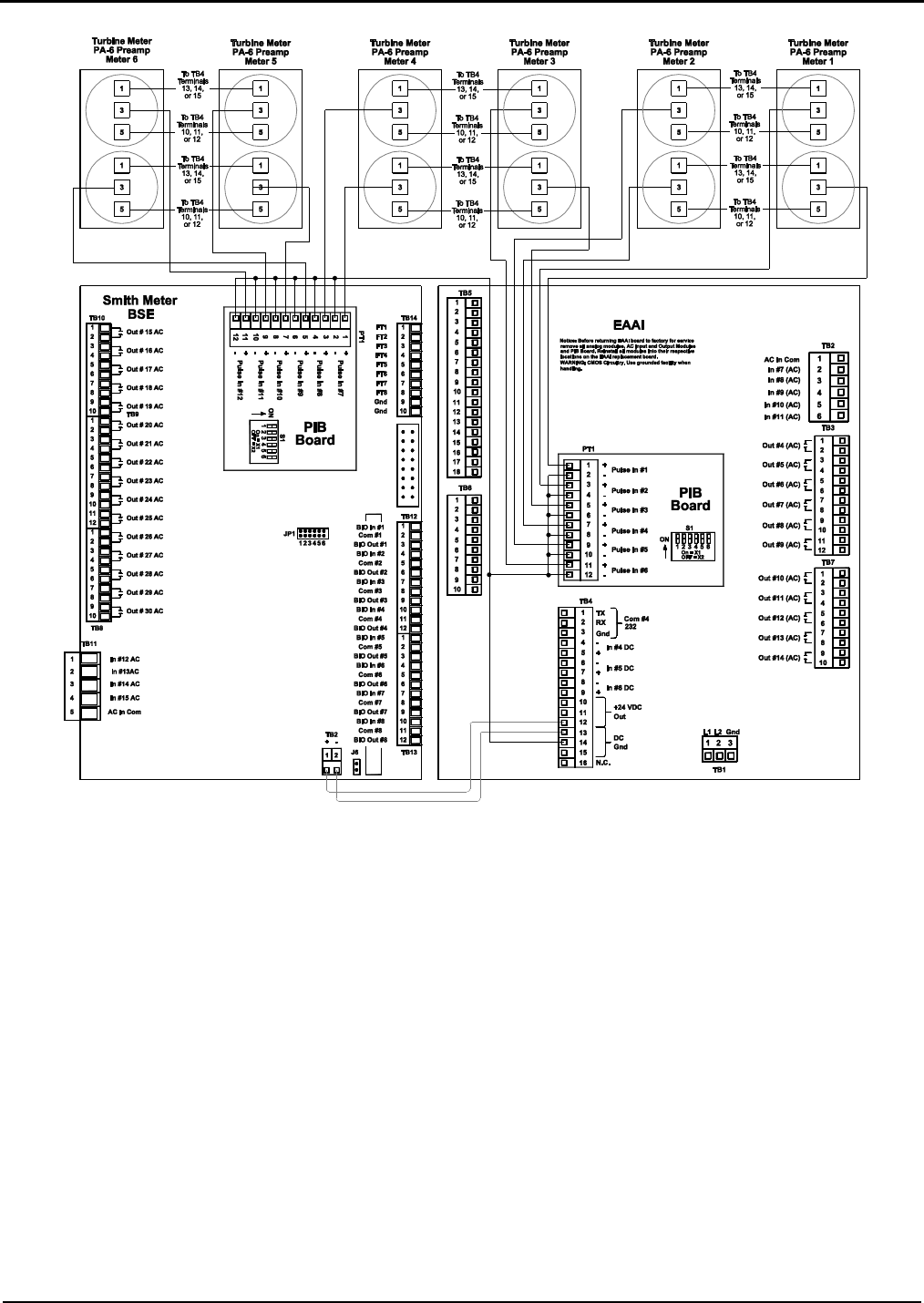
Figure 21. Wiring Diagram, Dual Pulse Turbine Meters with PA-6 Pre-amps (One Board Set)
Caution: For clarity, shields not shown. Connect shields to Terminals 3, 13, 14, or 15 of Terminal Block 4.
Note: Wiring between transmitter and AccuLoad should be done using a shielded cable per each transmitter. If selected cable utilizes twisted
pairs, do not run more than one signal in a twisted pair.
Caution: Each board set should be handled individually and contains its own “unique” 24v DC power supply. All
external devices such as pulse transmitters, RTD’s, 4-20mA devices and communication wiring that interface with a
board set MUST be powered by the +24VDC supplied by that board set and all the grounds including shield wires
must be connected/isolated to that board set, including the associated +24VDC distribution block. A sharing of power
supplies and grounding between board sets can cause ground loops leading to communication problems, external
device issues and instability of the DC power supply output from the EAAI board.
Note: The 24-volt power for the transmitters can be wired through the terminal block located in the bottom of the cabinet, as shown in Figure 5.
PA-6 Terminal Connections (Pre-amp #1)
1: Common
3: Signal A Output
5: Input Power
PA-6 Terminal Connections (Pre-amp #2)
1: Common
3: Signal B Output
5: Input Power

Section IV – Diagrams
32 MN06140 Issue/Rev. 0.6 (8/15)
Promass 80, 83, and 84 Coriolis Meters
When connecting the Promass 84 (does not apply to the Promass 80 or 83 models) to an AccuLoad it is important
that the “Line Monitoring” function on the Promass 84 be disabled. This is because the pulse input circuitry of the
AccuLoad requires the input pulse “off” voltage to be less than one volt (and the “on” voltage to be greater than 5
volts). If the “Line Monitoring” on the Promass 84 is enabled, the “off” voltage of the pulses will be greater than one volt
and therefore will be counted by the AccuLoad. There are three jumpers on each of the frequency output submodules on
the I/O board that enable/disable the “Line Monitoring” function. The factory default is to enable “Line Monitoring”.
Follow the steps from section 6.4.2 of the Proline Promass 84 Operating Instructions – Bulletin MN0M032 to
enable/disable this function.
Use this table to determine if the Promass can be wired for single or dual pulse output and the terminal number
corresponding to each unique model. The wiring diagrams are shown on the following pages.
Transmitter/Sensor
Modeling
+ Terminal
- Terminal
80XXX
-X-XXX-X-X-X-X-X-X-X-A
24
25
80XXX
-X-XXX-X-X-X-X-X-X-X-D
24
25
80XXX
-X-XXX-X-X-X-X-X-X-X-S
24
25
80XXX
-X-XXX-X-X-X-X-X-X-X-T
24
25
80XXX
-X-XXX-X-X-X-X-X-X-X-8
22
23
83XXX
-X-XXX-X-X-X-X-X-X-X-A
24
25
83XXX
-X-XXX-X-X-X-X-X-X-X-B
24
25
83XXX
-X-XXX-X-X-X-X-X-X-X-S
24
25
83XXX
-X-XXX-X-X-X-X-X-X-X-T
24
25
83XXX
-X-XXX-X-X-X-X-X-X-X-C
24
25
83XXX
-X-XXX-X-X-X-X-X-X-X-D
24
25
83XXX
-X-XXX-X-X-X-X-X-X-X-N
22
23
83XXX
-X-XXX-X-X-X-X-X-X-X-P
22
23
83XXX
-X-XXX-X-X-X-X-X-X-X-2
24
25
83XXX
-X-XXX-X-X-X-X-X-X-X-4
24
25
83XXX
-X-XXX-X-X-X-X-X-X-X-5
24
25
84XXX
-X-XXX-X-X-X-X-X-X-X-S
24
25
84XXX
-X-XXX-X-X-X-X-X-X-X-T
24
25
84XXX
-X-XXX-X-X-X-X-X-X-X-N
22
23
84XXX
-X-XXX-X-X-X-X-X-X-X-D
24
25
84XXX
-X-XXX-X-X-X-X-X-X-X-2
24
25
Table 8. Promass Modeling for Single Pulse Wiring
Transmitter/Sensor
Modeling
+ Terminal
- Terminal
83XXX
-X-XXX-X-X-X-X-X-X-X-M
22, 24
23, 25
84XXX
-X-XXX-X-X-X-X-X-X-X-M
22, 24
23, 25
84XXX
-X-XXX-X-X-X-X-X-X-X-1
22, 24
23, 25
Table 9. Promass Modeling for Dual Pulse Wiring
Note: In dual pulse mode, Output 1 (24/25) leads Output 2 (22/23) when flowing in the forward direction.
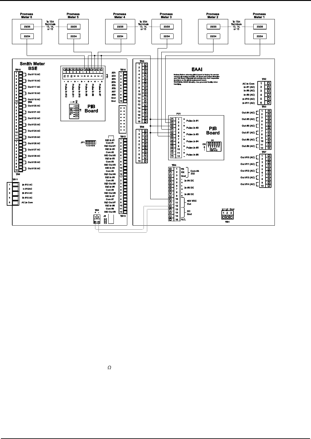
Section IV – Diagrams
MN06140 Issue/Rev. 0.6 (8/15) 33
Figure 22. Wiring Diagram, Promass 80, 83, and 84 Single Pulse
Caution: For clarity, shields not shown. Connect shields to Terminals 3, 13, 14, or 15 of Terminal Block 4.
Note: Wiring between transmitter and AccuLoad should be done using a shielded cable per each transmitter. If selected cable utilizes twisted
pairs, do not run more than one signal in a twisted pair.
Caution: Each board set should be handled individually and contains its own “unique” 24v DC power supply. All
external devices such as pulse transmitters, RTD’s, 4-20mA devices and communication wiring that interface with a
board set MUST be powered by the +24VDC supplied by that board set and all the grounds including shield wires
must be connected/isolated to that board set, including the associated +24VDC distribution block. A sharing of power
supplies and grounding between board sets can cause ground loops leading to communication problems, external
device issues and instability of the DC power supply output from the EAAI board.
Promass Wire Codes:
Terminal 22/24: +
Terminal 23/25: -
Note: The pulse input circuitry on the PIB has 1.6k of current limiting resistance “built-in” so that an external pull-up resistor is not required when
an open collector output device is connected as shown.
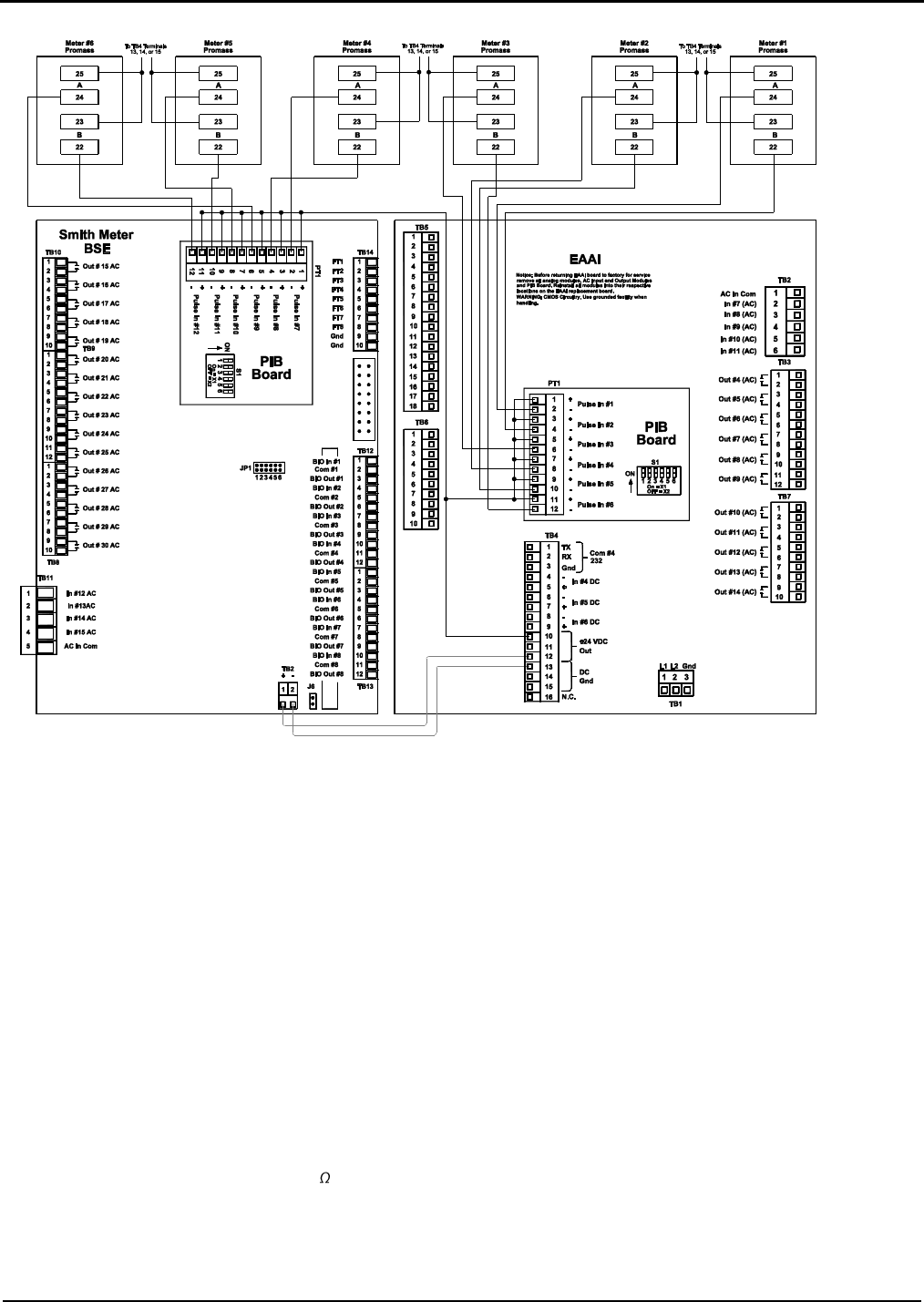
Section IV – Diagrams
34 MN06140 Issue/Rev. 0.6 (8/15)
Figure 23. Wiring Diagram, Promass 83 and 84 Dual Pulse
Caution: For clarity, shields not shown. Connect shields to Terminals 3, 13, 14, or 15 of Terminal Block 4.
Note: Wiring between transmitter and AccuLoad should be done using a shielded cable per each transmitter. If selected cable utilizes twisted
pairs, do not run more than one signal in a twisted pair.
Caution: Each board set should be handled individually and contains its own “unique” 24v DC power supply. All
external devices such as pulse transmitters, RTD’s, 4-20mA devices and communication wiring that interface with a
board set MUST be powered by the +24VDC supplied by that board set and all the grounds including shield wires
must be connected/isolated to that board set, including the associated +24VDC distribution block. A sharing of power
supplies and grounding between board sets can cause ground loops leading to communication problems, external
device issues and instability of the DC power supply output from the EAAI board.
Promass Wire Codes:
Terminal 22: Output 2+
Terminal 23: Output 2-
Terminal 24: Output 1+
Terminal 25: Output 1-
Note: The pulse input circuitry on the PIB has 1.6k of current limiting resistance “built-in” so that an external pull-up resistor is not required when
an open collector output device is connected as shown.
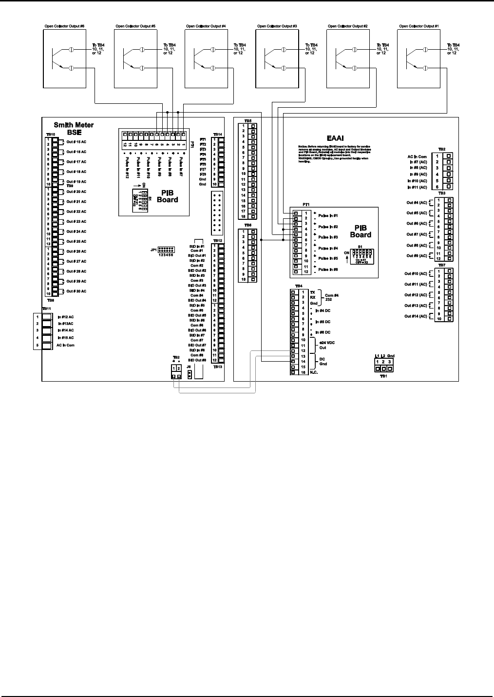
Section IV – Diagrams
MN06140 Issue/Rev. 0.6 (8/15) 35
Figure 24. Wiring Diagram, Optically Isolated Open Collector Output (One Board Set)
Caution: For clarity, shields not shown. Connect shields to Terminals 3, 13, 14, or 15 of Terminal Block 4.
Note: Wiring between transmitter and AccuLoad should be done using a shielded cable per each transmitter. If selected cable utilizes twisted
pairs, do not run more than one signal in a twisted pair.
Caution: Each board set should be handled individually and contains its own “unique” 24v DC power supply. All
external devices such as pulse transmitters, RTD’s, 4-20mA devices and communication wiring that interface with a
board set MUST be powered by the +24VDC supplied by that board set and all the grounds including shield wires
must be connected/isolated to that board set, including the associated +24VDC distribution block. A sharing of power
supplies and grounding between board sets can cause ground loops leading to communication problems, external
device issues and instability of the DC power supply output from the EAAI board.
Note: This diagram assumes that each output’s collector and emitter are isolated.
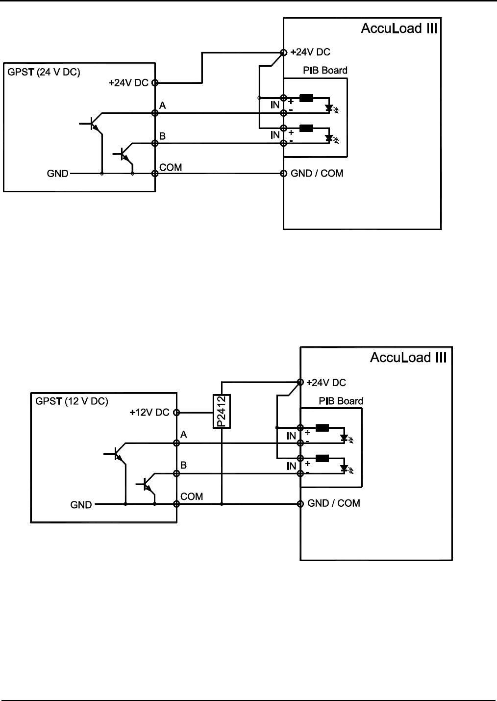
Section IV – Diagrams
36 MN06140 Issue/Rev. 0.6 (8/15)
Figure 25. Wiring Diagram, GPST Dual Pulse Transmitter + 24 Vdc with Open Collector Output with
Common Ground
Caution: For clarity, shields not shown. Connect shields to Terminals 3, 13, 14, or 15 of Terminal Block 4.
Note: Wiring between transmitter and AccuLoad should be done using a shielded cable per each transmitter. If selected cable utilizes twisted
pairs, do not run more than one signal in a twisted pair.
Figure 26. Wiring Diagram, GPST Dual Pulse Transmitter + 12 Vdc with Open Collector Output with
Common Ground Converter P2412 see MN06117.
Caution: For clarity, shields not shown. Connect shields to Terminals 3, 13, 14, or 15 of Terminal Block 4.
Note: Wiring between transmitter and AccuLoad should be done using a shielded cable per each transmitter. If selected cable utilizes twisted
pairs, do not run more than one signal in a twisted pair.
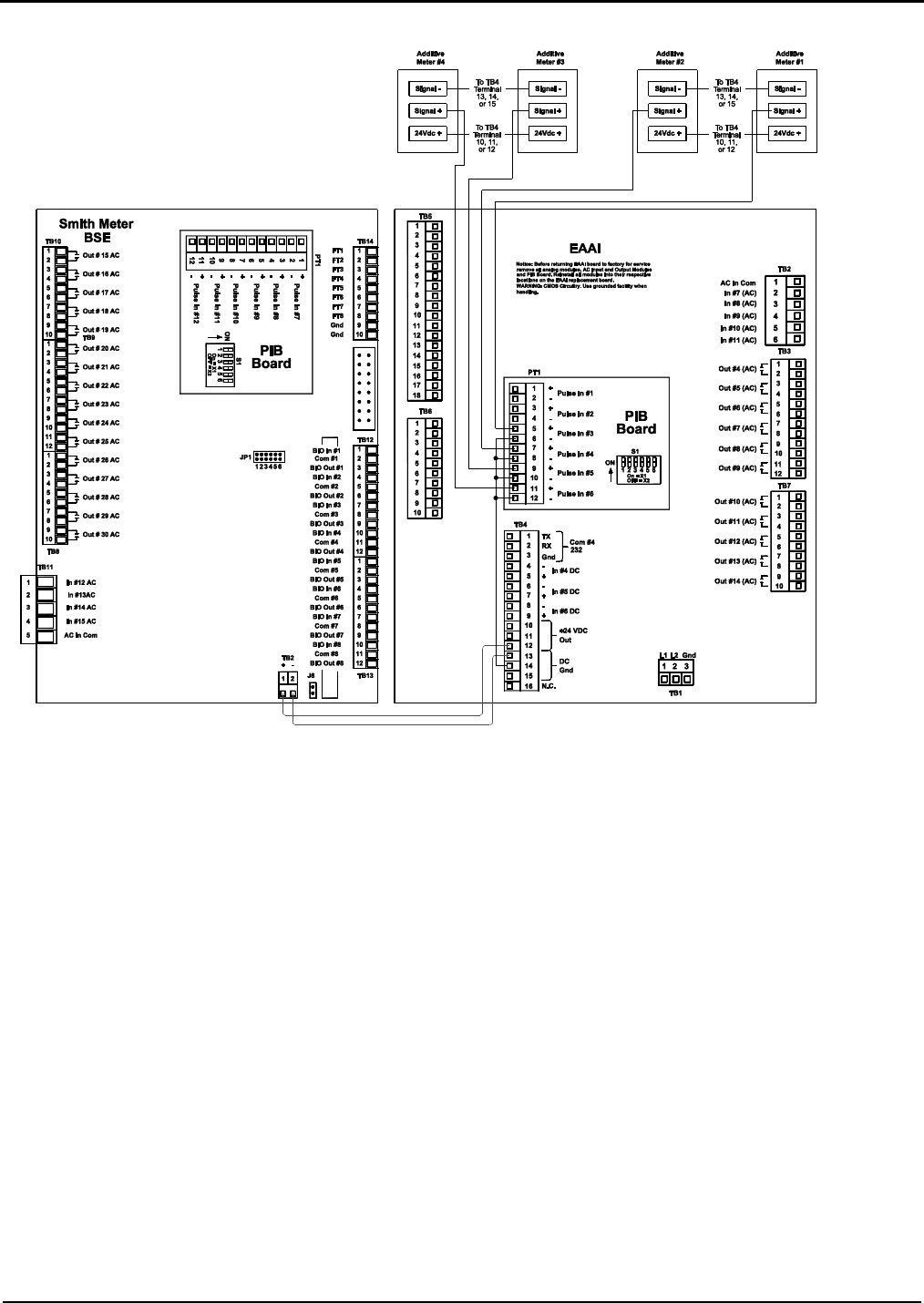
Section IV – Diagrams
MN06140 Issue/Rev. 0.6 (8/15) 37
Figure 27. Wiring Diagram, Four Additive Meters, Active Outputs (One Board Set)
This diagram is valid only when using one or two product meters. For other setups refer to table 6 for available
wiring connections.
Caution: For clarity, shields not shown. Connect shields to Terminals 3, 13, 14, or 15 of Terminal Block 4.
Note: Wiring between transmitter and AccuLoad should be done using a shielded cable per each transmitter. If selected cable utilizes twisted
pairs, do not run more than one signal in a twisted pair.
Caution: Each board set should be handled individually and contains its own “unique” 24v DC power supply. All
external devices such as pulse transmitters, RTD’s, 4-20mA devices and communication wiring that interface with a
board set MUST be powered by the +24VDC supplied by that board set and all the grounds including shield wires
must be connected/isolated to that board set, including the associated +24VDC distribution block. A sharing of power
supplies and grounding between board sets can cause ground loops leading to communication problems, external
device issues and instability of the DC power supply output from the EAAI board.
Note: The 24-volt power for the transmitters can be wired through the terminal block located in the bottom of the cabinet, as shown in Figure 5.
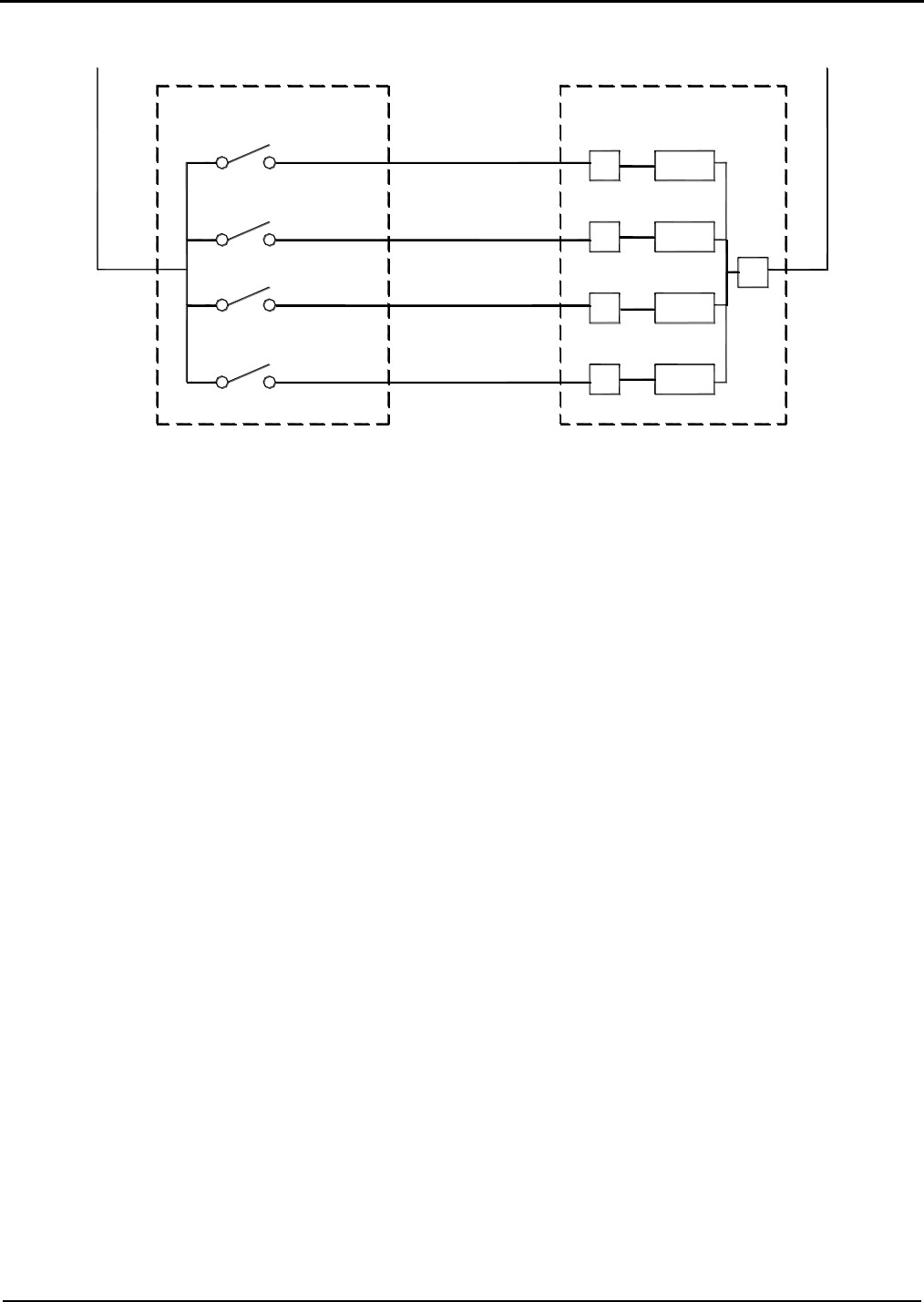
Section IV – Diagrams
38 MN06140 Issue/Rev. 0.6 (8/15)
Figure 28. Typical Additive Feedback Wiring
Voltage
Sense
Voltage
Sense
Voltage
Sense
Voltage
Sense
AccuLoad III
Injector Feedback Switches
#1
#2
#3
#4
Arm #1
Input #___
Input #___
Input #___
Input #___
N or L2
L1
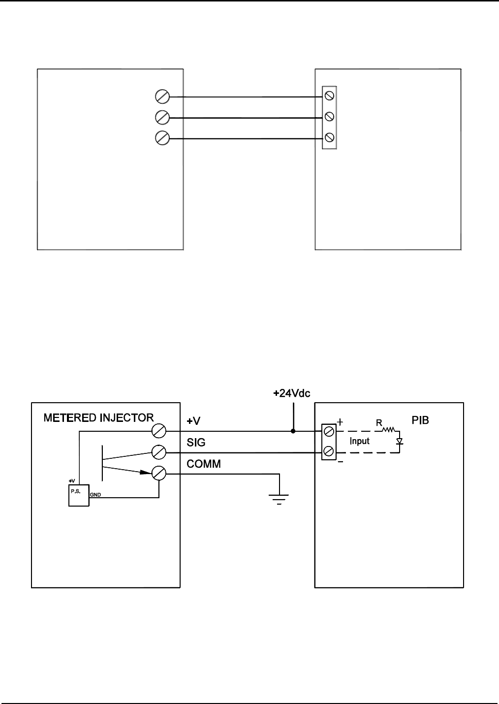
Section IV – Diagrams
MN06140 Issue/Rev. 0.6 (8/15) 39
Note: COMM is
connected to digital ground
(neg side of +24 VDC)
Figure 29. Monoblock to AICB Wiring Diagram
Caution: For clarity, shields not shown. Connect shields to Terminals 3, 13, 14, or 15 of Terminal Block 4.
Figure 30. Monoblock to PIB Wiring Diagram
Caution: For clarity, shields not shown. Connect shields to Terminals 3, 13, 14, or 15 of Terminal Block 4.
MONOBLOCK AICB
+V
SIG
COMM
V+
SIG
COMM
Gate City Monoblock Additive Meter
Typical Metered Injector Additive Meter
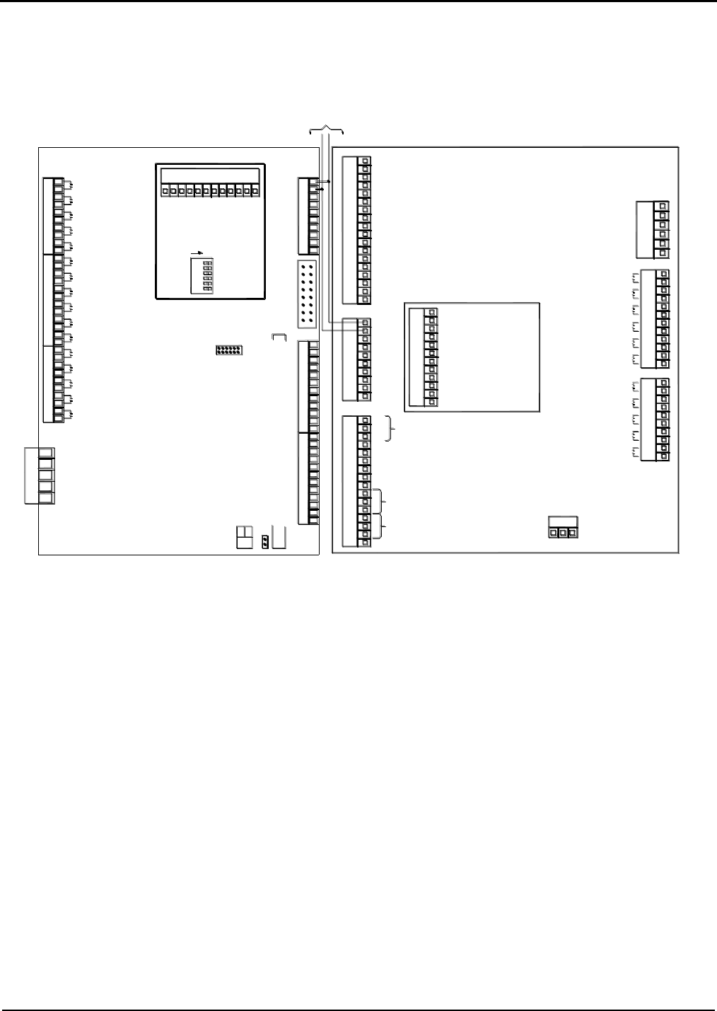
Section IV – Diagrams
40 MN06140 Issue/Rev. 0.6 (8/15)
Figure 31. Wiring Diagram, High Speed Prover Output (Open Collector Opto Coupler)
Caution: For clarity, shields not shown. Connect shields to Terminals 3, 13, 14, or 15 of Terminal Block 4.
EAAI
PIB
TB5
TB2
TB6
TB4
TB3
TB7
TB1
1
8
10
9
7
6
5
4
3
2
13
18
17
16
15
14
11
12
3
7
10
9
8
5
6
4
1
2
3
14
16
15
12
13
11
7
10
9
8
5
6
4
1
2
3
5
6
4
1
2
3
12
11
7
10
9
8
5
6
4
1
2
3
7
10
9
8
5
6
4
1
2
1 2 3
+
-
+
-
+
-
+
-
-
+
-
+
Pulse In #1
Pulse In #2
Pulse In #4
Pulse In #3
Pulse In #6
Pulse In #5
3
12
11
7
10
9
8
5
6
4
1
2
PT1
TX
RX
Gnd
+
-
+
-
-
N.C.
+24 VDC
Out
DC
Gnd
In #4 DC
In #5 DC
In #6 DC
Com #4
232
L1 GndL2
AC in Com
In #7 (AC)
In #8 (AC)
In #9 (AC)
In #10 (AC)
In #11 (AC)
Out #4 (AC)
Out #5 (AC)
Out #6 (AC)
Out #7 (AC)
Out #8 (AC)
Out #9 (AC)
Out #10 (AC)
Out #11 (AC)
Out #12 (AC)
Out #13 (AC)
Out #14 (AC)
Notice: Before returning EAAI board to factory for service
remove all analog modules, AC Input and Output Modules
and PIB Board. Reinstall all modules into their respective
locations on the EAAI replacement board.
WARNING: CMOS Circuitry. Use grounded facility when
handling.
+
Com #6 5
AC In Com
In #15 AC
In #14 AC
5
4
3
BIO Out #8
Com #8
BIO In #8
BIO Out #7
Com #7
BIO In #7
BIO Out #6
TB2
-+
1
J6
2
12
TB13
9
11
10
7
8
6
Smith Meter
2
Out # 27 AC
10
In #13AC
In #12 AC
2
1
TB11
TB8
7
9
8
5
6
4
Out # 30 AC
Out # 29 AC
Out # 28 AC
9
12
1
2
3
11
10
Out # 26 AC
Out # 25 AC
Out # 24 AC
6
7
8
4
5
3
Out # 22 AC
Out # 23 AC
Out # 21 AC
BSE
6
Out # 17 AC
9
1
10
8
7
Out # 20 AC
Out # 19 AC
TB9
Out # 18 AC
4
5
3
TB10
1
2
Out # 16 AC
Out # 15 AC
Board
OFF = X2
On = X1
2
BIO In #6
BIO Out #5
Com #5
BIO In #5
BIO Out #4
Com #4
BIO In #4
BIO Out #3
Com #3
BIO In #3
BIO Out #2
Com #2
BIO In #2
BIO Out #1
Com #1
BIO In #1
6543
1
JP1
65432
S1
4
11
2
4
3
12
1
10
9
8
6
7
5
1
3
2
TB12
Gnd
Gnd
FT8
FT7
FT6
FT5
FT4
FT3
_
+
1
8
Pulse In #10
-
Pulse In #11
Pulse In #12
-
+
+
-
12
11
10
9
Pulse In #9
Pulse In #8
Pulse In #7
PIB
ON
3
+
+
+
-
-
5
7
6
4
-
+
1
2
PT1
6
9
10
8
7
4
5
3
TB14
1
2
High Speed Prover Output
Prover
Out
+
_
Prover
Out
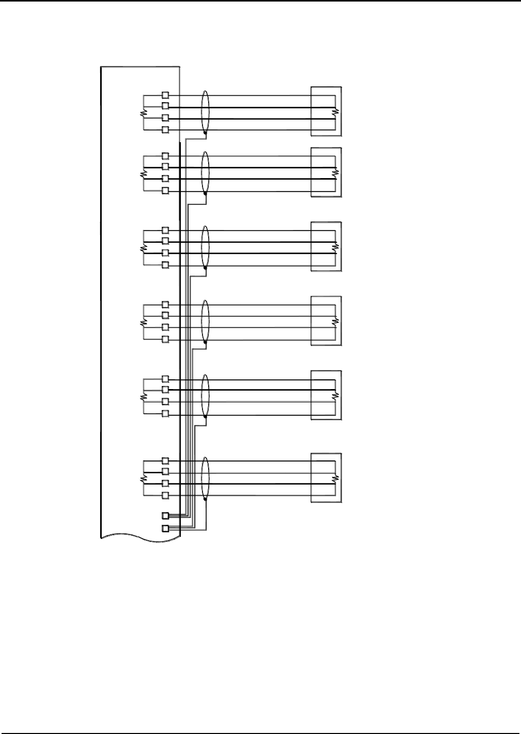
Section IV – Diagrams
MN06140 Issue/Rev. 0.6 (8/15) 41
Figure 32. Resistance (RTD) Input (One Board Set)
Caution: Each board set should be handled individually and contains its own “unique” 24v DC power supply. All
external devices such as pulse transmitters, RTD’s, 4-20mA devices and communication wiring that interface with a
board set MUST be powered by the +24VDC supplied by that board set and all the grounds including shield wires
must be connected/isolated to that board set, including the associated +24VDC distribution block. A sharing of power
supplies and grounding between board sets can cause ground loops leading to communication problems, external
device issues and instability of the DC power supply output from the EAAI board.
Note: If using two twisted pairs of wires, RTD+ and RTD– should be wired with one twisted pair. Sig+ and Sig– should be wired with another
twisted pair.
Used for temperature input from a platinum RTD. This input requires a four-wire connection to a platinum sensor with the following specification:
1. 100 Ω @ 0 Degrees Celsius.
2. 0.00385 Ω/Ω/Deg. C., DIN 43760, IEC 751, or BS1904, ITS-90
RTD +
SIG +
SIG -
RTD -
Ground (TB6)
AccuLoad III - EAAI
Red
Red
Black
Black
Terminal Block TB5
1
2
3
4
10
RTD -
SIG -
SIG +
RTD +
8
7
6
5
Probe Meter #2
Resistance Temperature
Black
Black
Red
Red
Probe Meter #1
Resistance Temperature
SIG -
RTD -
RTD +
SIG +
11
12
9
10
Black
Black
Resistance Temperature
Probe Meter #3
Red
Red
RTD -
RTD +
SIG +
SIG -
8
13
14
7
Probe Meter #4
Resistance Temperature
Black
Black
Red
Red
Terminal Block as noted
Ground (TB6) 9
TB6
TB5
TB5
TB6
TB6
5RTD +
SIG -
RTD -
SIG +
TB5
TB6
TB5
16
6
15
TB5
SIG +
RTD -
SIG -
TB6
TB5
RTD +
TB6
17
4
18
3
Red
Black
Black
Resistance Temperature
Probe Meter #5
Red
Red
Probe Meter #6
Resistance Temperature
Black
Black
Red
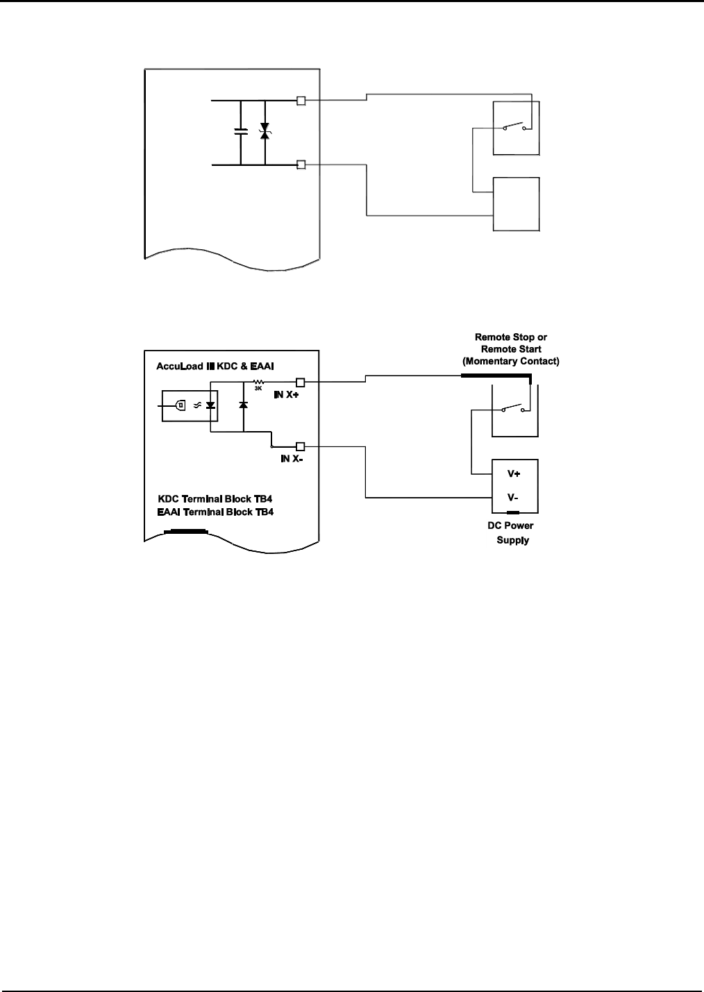
Section IV – Diagrams
42 MN06140 Issue/Rev. 0.6 (8/15)
Figure 33. AC Remote Start and Stop
Figure 34. DC Remote Start and Stop
IN X+
IN X-
AccuLoad III - EAAI
AC Power
Supply
L1
Terminal Block TB2
Remote Stop or
Remote Start
(Momentary Contact)
L2 or
Neutral
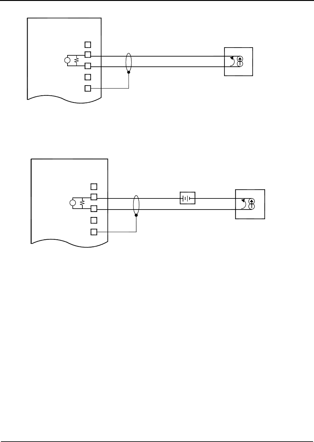
Section IV – Diagrams
MN06140 Issue/Rev. 0.6 (8/15) 43
Figure 35. 4-20mA Inputs (Active)
Figure 36. 4-20mA Inputs (Passive)
The 4-20mA inputs are isolated from the processor and main power and can be programmed for the function
required by the application. The analog inputs are also scalable through the I/O Configuration Menu of the unit.
The resolution of the input is 16 bits or one part in 65,536. The inputs should be wired with shielded twisted pairs
of wires of 18 to 24 gauge.
RTD +
SIG X +
SIG X -
RTD -
Ground (TB4)
AccuLoad III - EAAI
4-20mA
Transmitting Device
Vin
GND
Terminal Block TB5
RTD +
SIG X +
SIG X -
RTD -
Ground (TB4)
AccuLoad III - EAAI
4-20mA
Transmitting Device
Vin
GND
Terminal Block TB5
External
Power
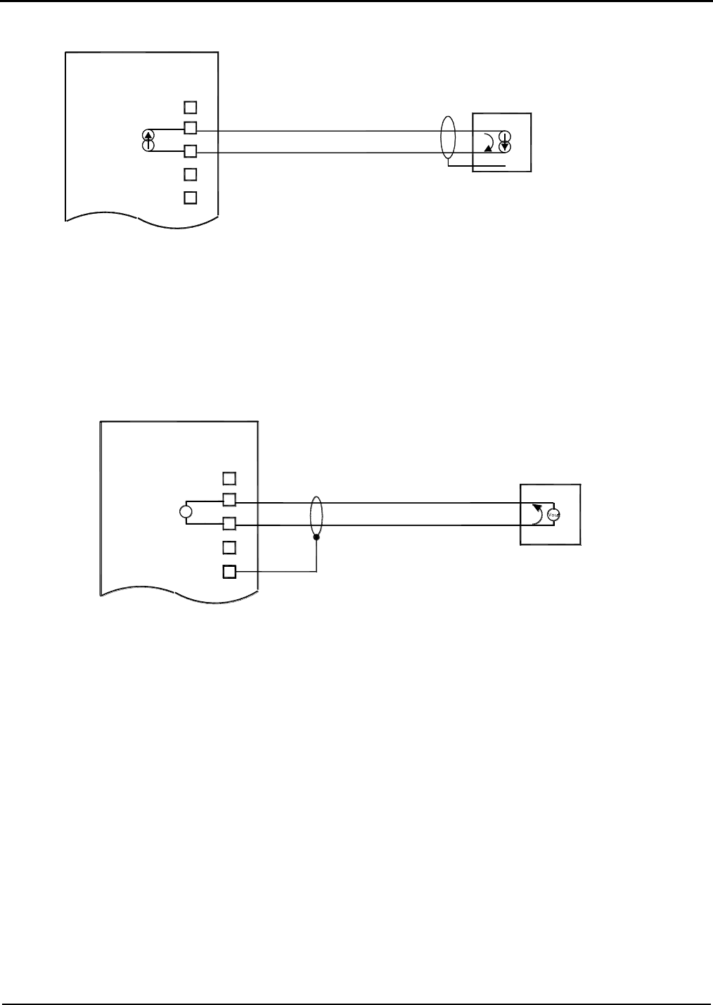
Section IV – Diagrams
44 MN06140 Issue/Rev. 0.6 (8/15)
Figure 37. 4-20mA Outputs
The 4-20mA outputs are isolated from the processor and main power and can be programmed for the function
required by the application. The analog outputs are also scalable through the I/O Configuration Menu of the unit.
The resolution of the output is 16 bits or one part in 65,536. The outputs should be wired with shielded twisted
pairs of wires of 18 to 24 gauge.
Figure 38. 1-5 Vdc Input
The 1-5 Vdc inputs are isolated from the processor and main power and can be programmed for the function
required by the application. The inputs are scalable through the I/O Configuration Menu of the unit. The resolution
of the input is 16 bits or one part in 65,536. The inputs should be wired with shielded twisted pairs of wires of 18
to 24 gauge.
RTD +
SIG X +
SIG X -
RTD -
Ground (TB4)
AccuLoad III - EAAI
1-5 Vdc
Transmitting Device
Vin
No Connection
No Connection
Terminal Block TB5
RTD +
SIG X +
SIG X -
RTD -
Ground (TB4)
AccuLoad III - EAAI
No Connection
No Connection
4-20mA
Receiving Device
Terminal Block TB5
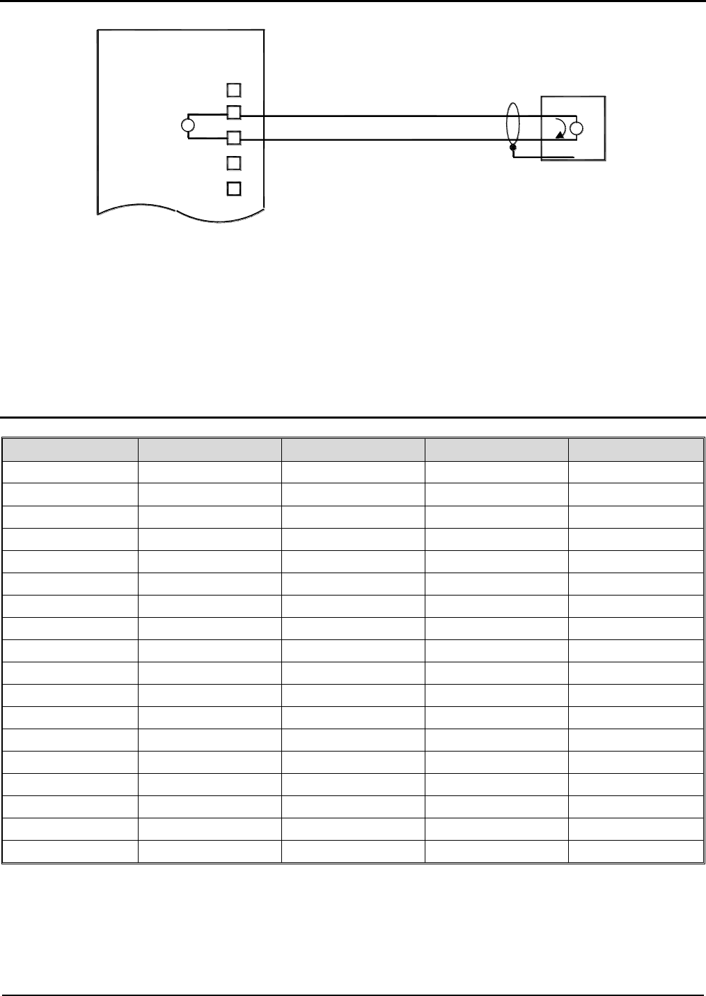
Section IV – Diagrams
MN06140 Issue/Rev. 0.6 (8/15) 45
Figure 39. 1-5 Vdc Output
The 1-5 Vdc outputs are isolated from the processor and main power and can be programmed for the function
required by the application. The outputs are also scalable through the I/O Configuration Menu of the unit. The
resolution of the output is 16 bits or one part in 65,536. The outputs should be wired with shielded twisted pairs of
wires of 18 to 20 gauge.
Wiring Terminals, 4-20mA and 1-5 Vdc Inputs/Outputs (One Board Set)
Module Number
Connection
Terminal Number
Board
Terminal Block
AM #1
+
2
EAAI
TB5
AM #1
-
3
EAAI
TB5
AM #1
Shield
3, 13, 14, or 15
EAAI
TB4
AM #2
+
6
EAAI
TB5
AM #2
-
7
EAAI
TB5
AM #2
Shield
3, 13, 14, or 15
EAAI
TB4
AM #3
+
10
EAAI
TB5
AM #3
-
11
EAAI
TB5
AM #3
Shield
3, 13, 14, or 15
EAAI
TB4
AM #4
+
13
EAAI
TB5
AM #4
-
14
EAAI
TB5
AM #4
Shield
3, 13, 14, or 15
EAAI
TB4
AM #5
+
15
EAAI
TB5
AM #5
-
16
EAAI
TB5
AM #5
Shield
3, 13, 14, or 15
EAAI
TB4
AM #6
+
17
EAAI
TB5
AM #6
-
18
EAAI
TB5
AM #6
Shield
3, 13, 14, or 15
EAAI
TB4
Table 10. Analog Terminal Connection
RTD +
SIG X +
SIG X -
RTD -
Ground (TB4)
AccuLoad III - EAAI
1-5 Vdc
Receiving Device
Vin
No Connection
No Connection
Vout
Terminal Block TB5
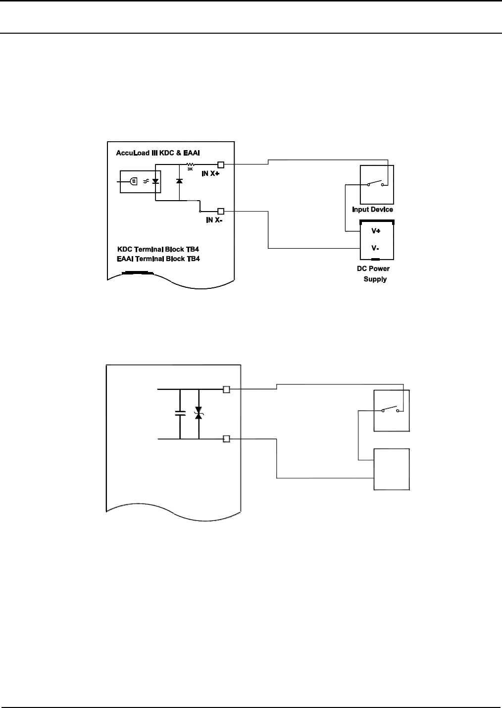
Section IV – Diagrams
46 MN06140 Issue/Rev. 0.6 (8/15)
Digital Inputs
Each set of boards is capable of providing fourteen DC digital inputs and nine AC digital inputs (standard). The
inputs can be programmed as to function through the configuration directory. Eight of the DC digital inputs are
bi-state and can be used as either inputs or outputs depending on how they are programmed and wired. Examples of
configurations for the digital inputs are permissives that have to be connected before the AccuLoad will allow the
driver to load, feedback from additive injectors, and swing arm permissive inputs (to ensure that the swing arm
and the ground are connected on the correct lane, etc.). For optional inputs, see AICB.
Figure 40. DC Inputs
Figure 41. AC Inputs
IN X+
IN X-
AccuLoad III - EAAI
AC Power
Supply
Input Device
V+
V-
Terminal Block TB2

Section IV – Diagrams
MN06140 Issue/Rev. 0.6 (8/15) 47
Wiring Terminals, Digital Inputs (One Board Set)
Input #
Voltage Type
Board
Terminal Block
Terminal
Input (+)
Connections
Common (-)
1
DC
KDC
TB4
1
2
2
DC
KDC
TB4
3
4
3
DC
KDC
TB4
5
6
4
DC
EAAI
TB4
5
4
5
DC
EAAI
TB4
7
6
6
DC
EAAI
TB4
9
8
7
AC
EAAI
TB2
2
1
8
AC
EAAI
TB2
3
1
9
AC
EAAI
TB2
4
1
10
AC
EAAI
TB2
5
1
11
AC
EAAI
TB2
6
1
12
AC
BSE
TB11
1
5
13
AC
BSE
TB11
2
5
14
AC
BSE
TB11
3
5
15
AC
BSE
TB11
4
5
Table 11. Digital Inputs
Caution: Each board set should be handled individually and contains its own “unique” 24v DC power supply. All
external devices such as pulse transmitters, RTD’s, 4-20mA devices and communication wiring that interface with
a board set MUST be powered by the +24VDC supplied by that board set and all the grounds including shield
wires must be connected/isolated to that board set, including the associated +24VDC distribution block. A sharing of
power supplies and grounding between board sets can cause ground loops leading to communication problems,
external device issues and instability of the DC power supply output from the EAAI board.
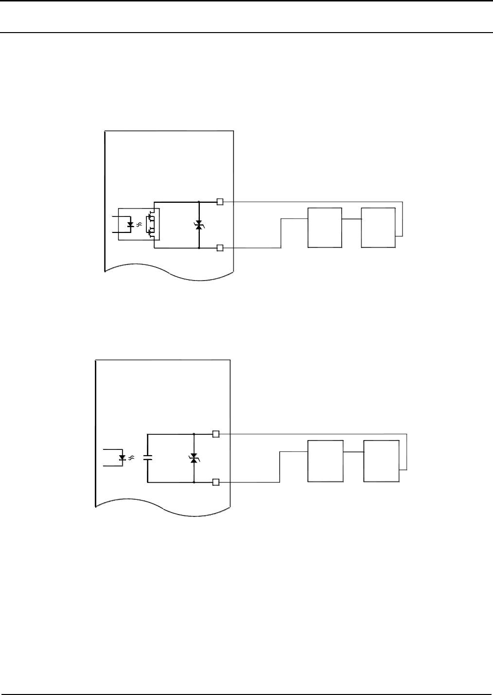
Section IV – Diagrams
48 MN06140 Issue/Rev. 0.6 (8/15)
Digital Outputs
Each set of boards is capable of providing eleven DC digital outputs and twenty-seven AC digital outputs (standard).
The outputs can be programmed as to function through the configuration directory. Eight of the DC digital outputs
are bi-state and can be used as either inputs or outputs depending on how they are programmed and wired. The
digital outputs are used to control the flow control valve, turn on the product pumps, turn on the additive pumps,
signal the additive injector to inject, etc. For optional outputs, see AICB.
Figure 42. DC Outputs
Figure 43. AC Outputs
Out X-
Out X+
AccuLoad III KDC
DC Power
SupplyDevice
V+
V-
Receiving
Alarm,
Valve,
Etc.
Terminal Block TB5
Out X-
Out X+
AccuLoad III - EAAI
AC Power
SupplyDevice
V+
V-
Receiving
Alarm,
Valve,
Etc.
Terminal Blocks TB3 & TB7

Section IV – Diagrams
MN06140 Issue/Rev. 0.6 (8/15) 49
Wiring Terminals, Digital Outputs (One Board Set)
Output #
Voltage Type
Board
Terminal Block
Terminal
Output (+)
Connections
Common (-)
1
DC
KDC
TB5
1
2
2
DC
KDC
TB5
3
4
3
DC
KDC
TB5
5
6
4
AC
EAAI
TB3
1
2
5
AC
EAAI
TB3
3
4
6
AC
EAAI
TB3
5
6
7
AC
EAAI
TB3
7
8
8
AC
EAAI
TB3
9
10
9
AC
EAAI
TB3
11
12
10
AC
EAAI
TB7
1
2
11
AC
EAAI
TB7
3
4
12
AC
EAAI
TB7
5
6
13
AC
EAAI
TB7
7
8
14
AC
EAAI
TB7
9
10
15
AC
BSE
TB10
1
2
16
AC
BSE
TB10
3
4
17
AC
BSE
TB10
5
6
18
AC
BSE
TB10
7
8
19
AC
BSE
TB10
9
10
20
AC
BSE
TB9
1
2
21
AC
BSE
TB9
3
4
22
AC
BSE
TB9
5
6
23
AC
BSE
TB9
7
8
24
AC
BSE
TB9
9
10
25
AC
BSE
TB9
11
12
26
AC
BSE
TB8
1
2
27
AC
BSE
TB8
3
4
28
AC
BSE
TB8
5
6
29
AC
BSE
TB8
7
8
30
AC
BSE
TB8
9
10
Table 12. Digital Outputs
Caution: Each board set should be handled individually and contains its own “unique” 24v DC power supply. All
external devices such as pulse transmitters, RTD’s, 4-20mA devices and communication wiring that interface with a
board set MUST be powered by the +24VDC supplied by that board set and all the grounds including shield wires
must be connected/isolated to that board set, including the associated +24VDC distribution block. A sharing of power
supplies and grounding between board sets can cause ground loops leading to communication problems, external
device issues and instability of the DC power supply output from the EAAI board.

Section IV – Diagrams
50 MN06140 Issue/Rev. 0.6 (8/15)
Input*
Output*
Voltage
Type
Board
Terminal
Block
Terminal Connections
Input +
Common -
Output +
16
31
DC
BSE
TB12
1
2
3
17
32
DC
BSE
TB12
4
5
6
18
33
DC
BSE
TB12
7
8
9
19
34
DC
BSE
TB12
10
11
12
20
35
DC
BSE
TB13
1
2
3
21
36
DC
BSE
TB13
4
5
6
22
37
DC
BSE
TB13
7
8
9
23
38
DC
BSE
TB13
10
11
12
Table 13. Bi-state Inputs/Outputs
*Note: Relay numbers for programming
Note: Refer to Table 5 to set JP1 on the BSE to match the number of inputs and outputs that are configured and wired.
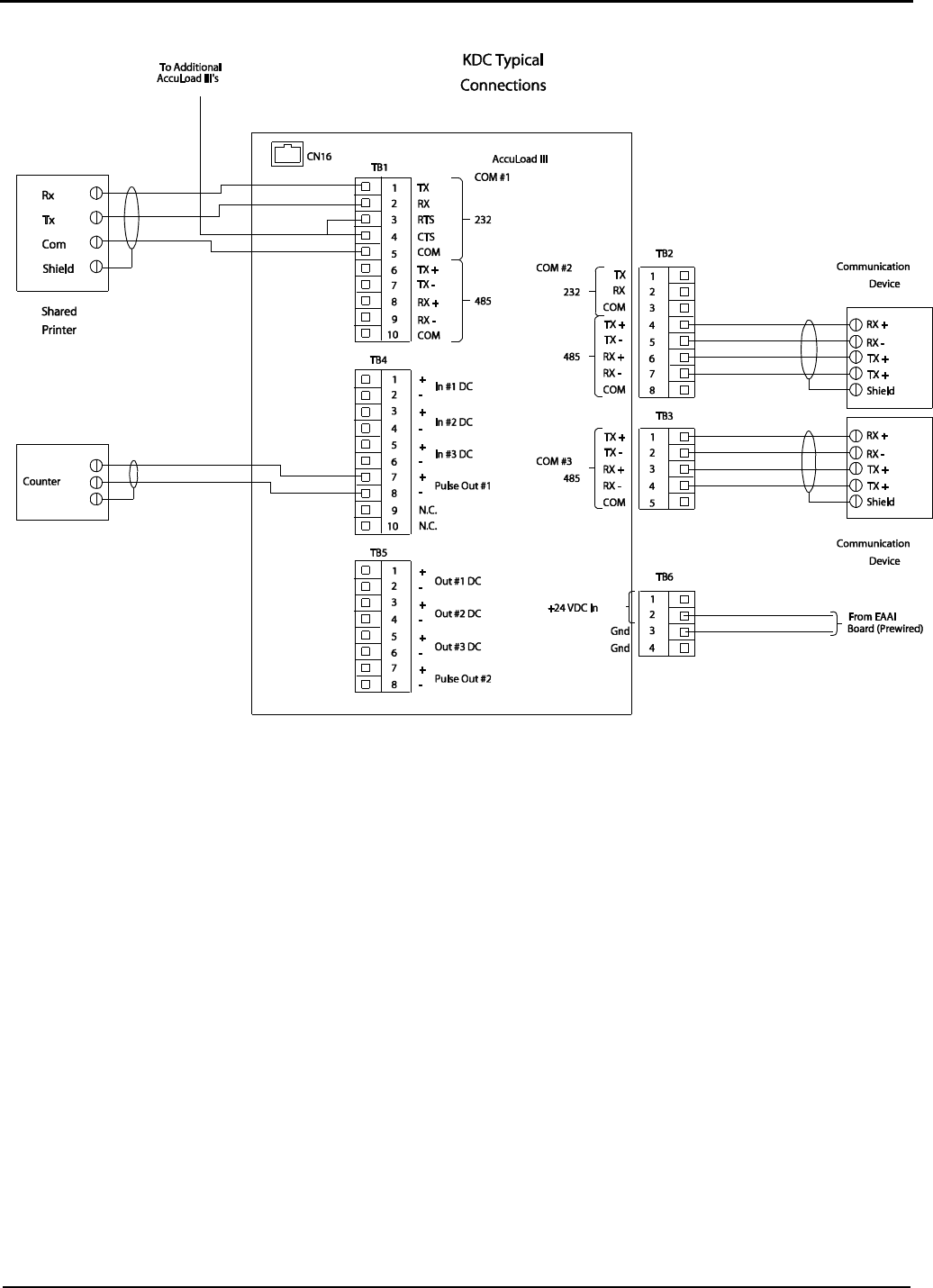
Section IV – Diagrams
MN06140 Issue/Rev. 0.6 (8/15) 51
Figure 44. KDC Typical Diagram (One Board Set in FCM)
Caution: Each board set should be handled individually and contains its own “unique” 24v DC power supply. All
external devices such as pulse transmitters, RTD’s, 4-20mA devices and communication wiring that interface with a
board set MUST be powered by the +24VDC supplied by that board set and all the grounds including shield wires
must be connected/isolated to that board set, including the associated +24VDC distribution block. A sharing of power
supplies and grounding between board sets can cause ground loops leading to communication problems, external
device issues and instability of the DC power supply output from the EAAI board.
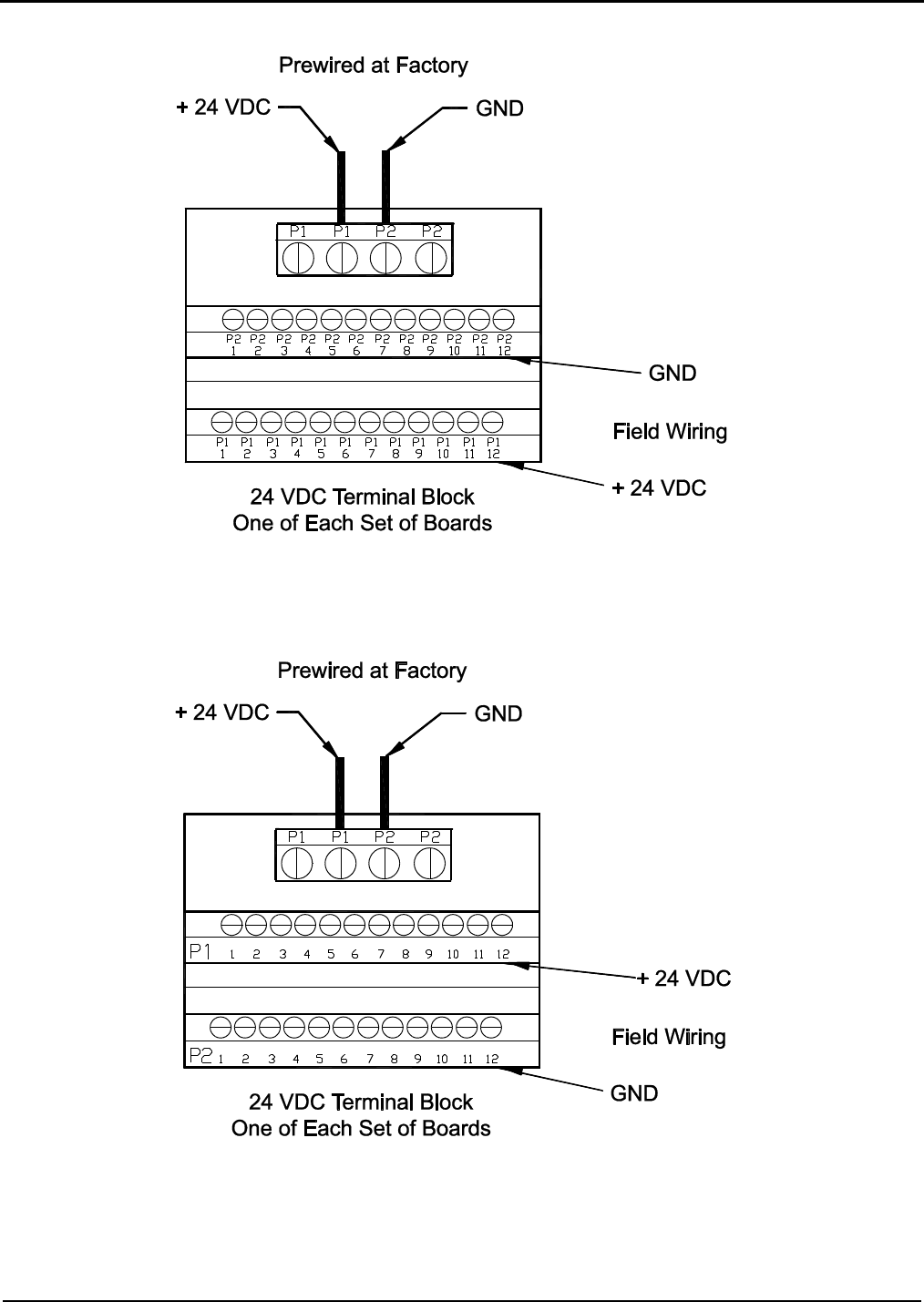
Section IV – Diagrams
52 MN06140 Issue/Rev. 0.6 (8/15)
Figure 45a. 24Vdc Terminal Block Diagram (units built before January 1, 2014)
Figure 45b. 24Vdc Terminal Block Diagram (units built after January 1, 2014)
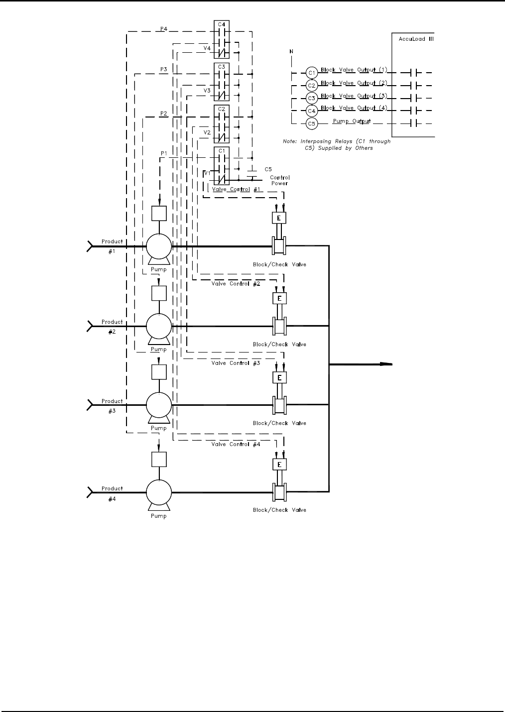
Section IV – Diagrams
MN06140 Issue/Rev. 0.6 (8/15) 53
Figure 46. Pump and Block Valve Wiring Diagram
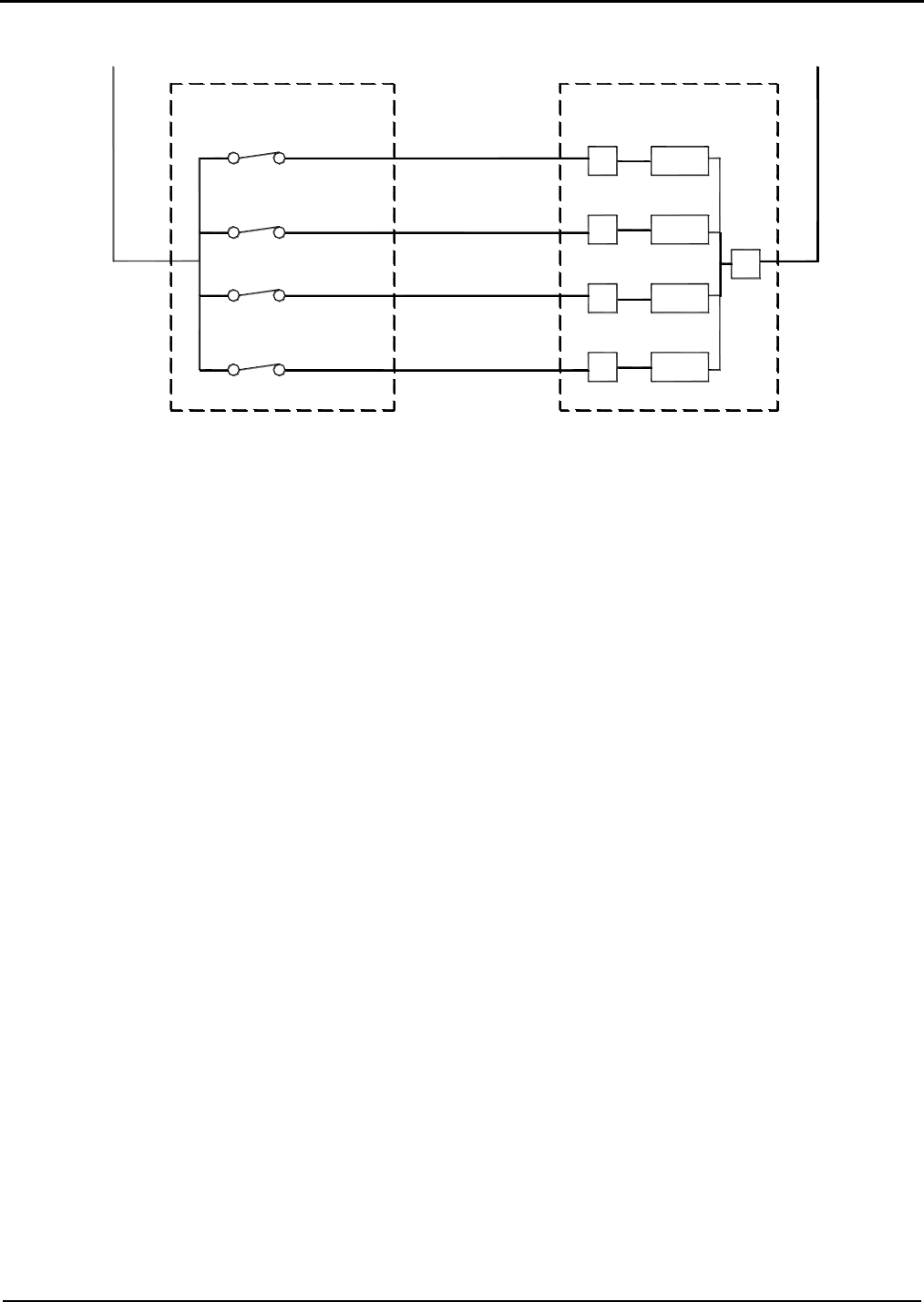
Section IV – Diagrams
54 MN06140 Issue/Rev. 0.6 (8/15)
Figure 47. Typical Block Valve Feedback Wiring
Voltage
Sense
Voltage
Sense
Voltage
Sense
Voltage
Sense
AccuLoad III
Valve Feedback Switches
#1
#2
#3
#4
Arm #1
Input #___
Input #___
Input #___
Input #___
N or L2
L1
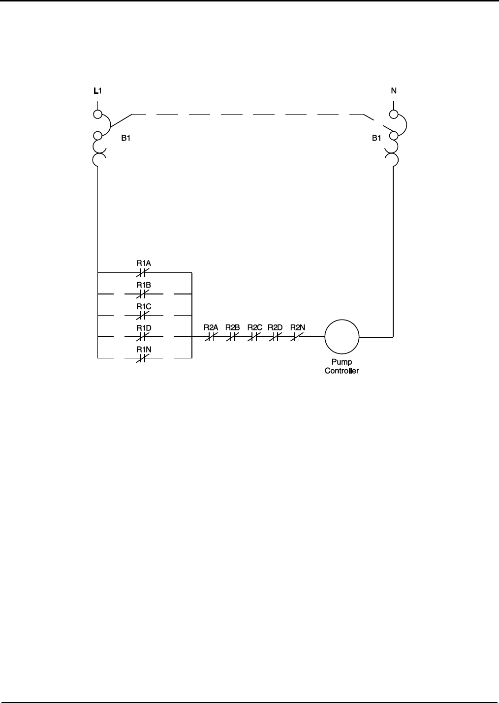
Section IV – Diagrams
MN06140 Issue/Rev. 0.6 (8/15) 55
Figure 48. Pump and Alarm Contact Wiring
Notes:
1. This figure shows wiring for a typical pump and alarm contact array for multiple AccuLoad controlled load arms, if the pump and alarm
control options are used.
2. R1A through R1N represents the contacts of the customer supplies relay (R1) on the output of the AccuLoad pump permissive contacts.
3. R2A through R2N represents the contacts of the customer supplied relay (R2) on the output of the AccuLoad alarm permissive contacts.
4. An interposing relay must be used between the pump controller and the AccuLoad pump contacts.
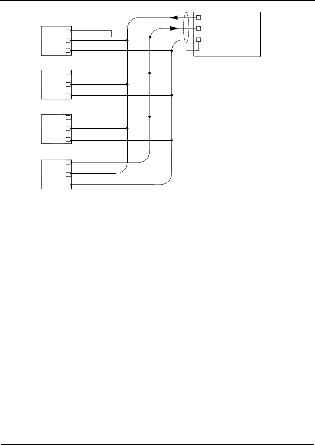
Section IV – Diagrams
56 MN06140 Issue/Rev. 0.6 (8/15)
Figure 49. MMI to FCM RS232 Comm Port Wiring (With Four Board Sets)
Tx (TB2)
Rx (TB2)
Com (TB2)
KDC Board Set A
Tx (TB2)
Rx (TB2)
Com (TB2)
Shield
MMI - KDC Board
KDC Board Set B
KDC Board Set C
KDC Board Set D
1
3
2
1
2
3
Com (TB2)
3
Tx (TB2)
Rx (TB2)
2
1
Rx (TB2)
Tx (TB2)
Com (TB2)
3
2
1
Com (TB2)
Tx (TB2)
Rx (TB2)
2
3
1
KDC Board Sets Located in FCM Cabinet
Wiring Shown as EIA-232 to Comm Port #2

Section IV – Diagrams
MN06140 Issue/Rev. 0.6 (8/15) 57
Figure 50. MMI to FCM 485 Comm Port Wiring (With Four Board Sets)
Tx+(TB2)
Rx+(TB2)
Com (TB2)
KDC Board Set A
Tx+(TB2)
Rx+(TB2)
Com (TB2)
Shield
MMI - KDC Board
KDC Board Set B
KDC Board Set C
KDC Board Set D
4
8
6
4
6
8
Com (TB2)
8
Tx+(TB2)
Rx+(TB2)
6
4
Rx+(TB2)
Tx+(TB2)
Com (TB2)
8
6
4
Com (TB2)
Tx+(TB2)
Rx+(TB2)
6
8
4
KDC Board Sets Located in FCM Cabinet
Wiring Shown as EIA-485 to Comm Port #2
5
7
Tx-(TB2)
Rx-(TB2)
5
7
Tx-(TB2)
Rx-(TB2)
Tx-(TB2)
Rx-(TB2)
7
5
5
7
Tx-(TB2)
Rx-(TB2)
5
7
Tx-(TB2)
Rx-(TB2)
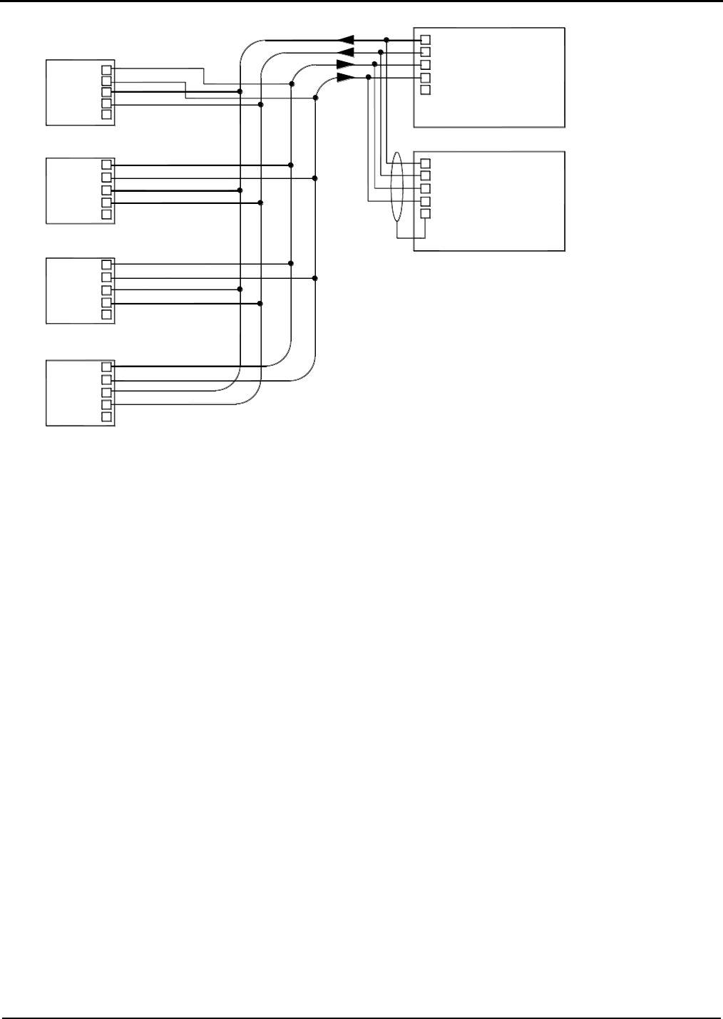
Section IV – Diagrams
58 MN06140 Issue/Rev. 0.6 (8/15)
Figure 51. Dual MMI 485 Comm Port Wiring (With Four Board Sets)
Tx+(TB2)
Rx+(TB2)
Com (TB2)
KDC Board Set A
Tx+(TB2)
Rx+(TB2)
Com (TB2)
Shield
MMI - KDC Board
KDC Board Set B
KDC Board Set C
KDC Board Set D
4
8
6
4
6
8
Com (TB2)
8
Tx+(TB2)
Rx+(TB2)
6
4
Rx+(TB2)
Tx+(TB2)
Com (TB2)
8
6
4
Com (TB2)
Tx+(TB2)
Rx+(TB2)
6
8
4
KDC Board Sets Located in FCM Cabinet
Wiring Shown as EIA-485 to Comm Port #2
5
7
Tx-(TB2)
Rx-(TB2)
5
7
Tx-(TB2)
Rx-(TB2)
Tx-(TB2)
Rx-(TB2)
7
5
5
7
Tx-(TB2)
Rx-(TB2)
5
7
Tx-(TB2)
Rx-(TB2)
Shield
2nd MMI - KDC Board (Swing Arm Applications)
Rx-(TB2)
Tx-(TB2)
Com (TB2)
Rx+(TB2)
Tx+(TB2)
4
7
5
6
8
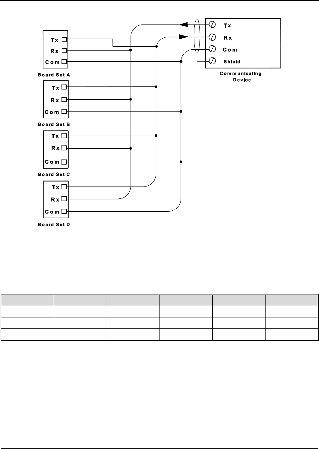
Section IV – Diagrams
MN06140 Issue/Rev. 0.6 (8/15) 59
Figure 52. EIA-232 Multi-Drop Communications
The figure shows the typical wiring scheme for multi-drop communications between a communications device
(other than the MMI) and the AccuLoad III. Refer to the table below for pin numbers on each of the EIA-232
communication ports. Note that the shield is to be terminated at the communication device.
Comm Port
Tx
Rx
Common
Board
Terminal Block
1
1
2
5
KDC
TB1
2*
1
2
3
KDC
TB2
4
1
2
3
EAAI
TB4
Table 14. EIA 232 Communication Ports
Note: Communications Ports 1 and 2 can be either EIA-232 or EIA-485.
*Normally used for MMI Communications
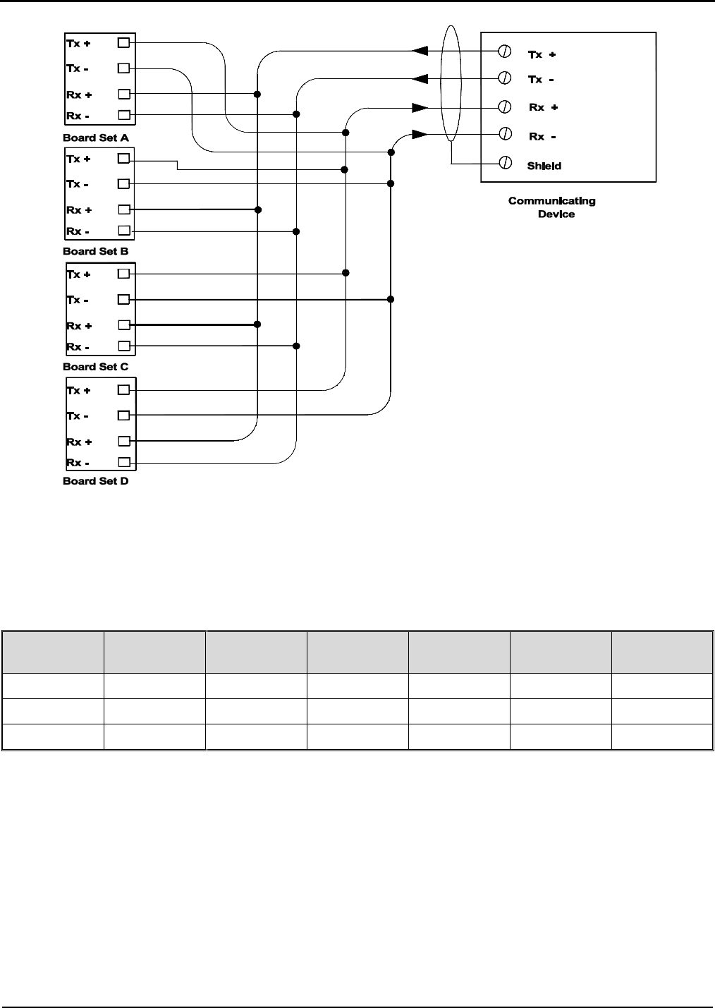
Section IV – Diagrams
60 MN06140 Issue/Rev. 0.6 (8/15)
Figure 53. EIA-485 Multi-Drop Communications
The figure shows the typical wiring scheme for multi-drop communications between a communications device
(other than the MMI) and the AccuLoad. Refer to the table below for pin numbers on each of the EIA-485
communication ports. Note that the shield is to be terminated at the communication device.
Comm Port
Tx +
Tx -
Rx +
Rx -
Board
Terminal
Block
1
6
7
8
9
KDC
TB1
2*
4
5
6
7
KDC
TB2
3
1
2
3
4
KDC
TB3
Table 14. EIA 485 Communication Ports
Note: Communications Ports 1 and 2 can be either EIA-485 or EIA-232.
*Normally used for MMI communications
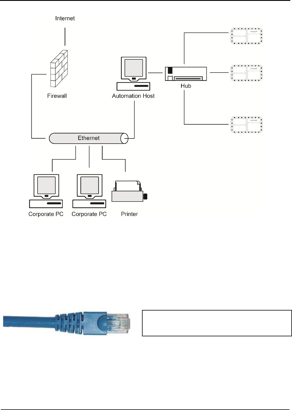
Section IV – Diagrams
MN06140 Issue/Rev. 0.6 (8/15) 61
Figure 54. Network configuration for multiple AccuLoads connected via a hub then linked directly to the
automation system and LAN.
Refer to the standards IEEE 802.X states for wiring and using Ethernet connectivity rules and regulations. Utilize
standard IT practices and protocol when connecting several AccuLoads to any type of hub, router, or switching
device. There are various connectivity configurations and the responsibility of each configuration is left to each
individual. Distances, transmission time, etc. will all follow the standard IEEE spec rating. If there are any questions
regarding installation of multiple AccuLoads over Ethernet communications, please consult the factory.
Employ the standard CAT 5 Cable, used for connecting
an AccuLoad to any router, switch, or hub.
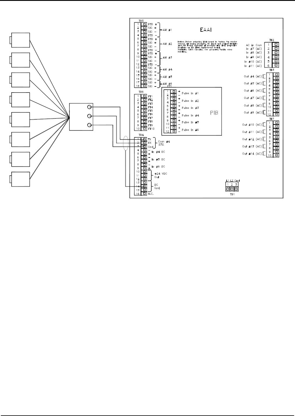
Section IV – Diagrams
62 MN06140 Issue/Rev. 0.6 (8/15)
Figure 55. Lubrizol EIA-232 Communications (One Board Set)
Caution: Each board set should be handled individually and contains its own “unique” 24v DC power supply. All
external devices such as pulse transmitters, RTD’s, 4-20mA devices and communication wiring that interface with a
board set MUST be powered by the +24VDC supplied by that board set and all the grounds including shield wires
must be connected/isolated to that board set, including the associated +24VDC distribution block. A sharing of power
supplies and grounding between board sets can cause ground loops leading to communication problems, external
device issues and instability of the DC power supply output from the EAAI board.
Tx
Rx
Com
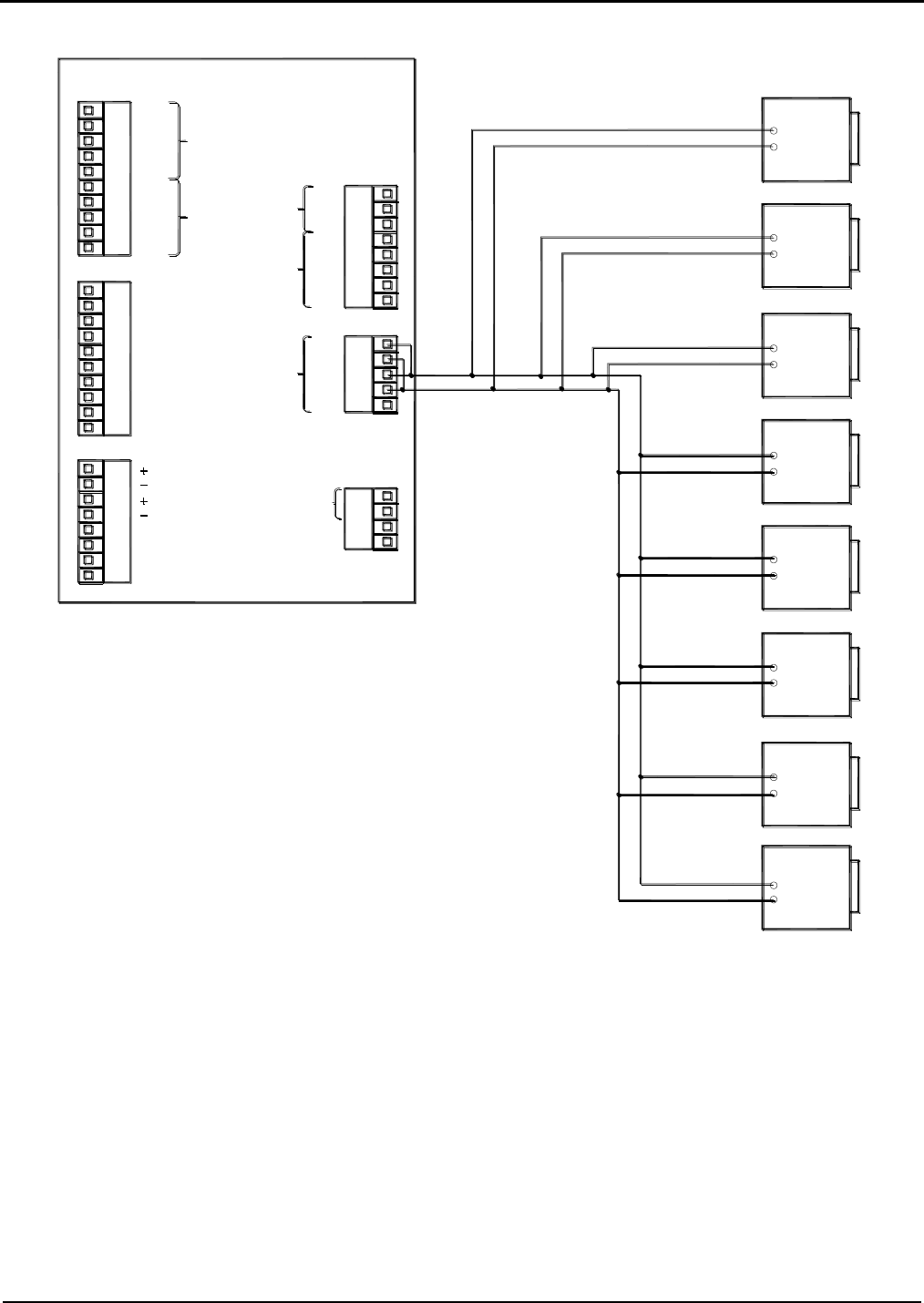
Section IV – Diagrams
MN06140 Issue/Rev. 0.6 (8/15) 63
Figure 56. Lubrizol EIA-485 (Two-Wire) Communications (One Board Set)
Caution: Each board set should be handled individually and contains its own “unique” 24v DC power supply. All
external devices such as pulse transmitters, RTD’s, 4-20mA devices and communication wiring that interface with a
board set MUST be powered by the +24VDC supplied by that board set and all the grounds including shield wires
must be connected/isolated to that board set, including the associated +24VDC distribution block. A sharing of power
supplies and grounding between board sets can cause ground loops leading to communication problems, external
device issues and instability of the DC power supply output from the EAAI board.
Additive Systems
-
+
+
-
+
-
+
-
+
-
-
+
-
+
-
+
KDC
TB1
TB4
TB5
TB6
TB3
TB2
1
2
3
4
5
6
7
8
9
10
1
8
10
9
7
6
5
4
3
2
4
8
7
6
5
2
3
1
7
8
5
6
4
3
2
1
3
5
4
1
2
4
2
3
1
TX
RX
RTS
CTS
COM
TX +
TX -
RX +
RX -
COM
232
485
COM #1
+
-
+
-
+
-
+
-
N.C.
N.C.
In #1 DC
In #2 DC
In #3 DC
Pulse Out #1
Out #1 DC
Out #2 DC
Out #3 DC
+
-
Pulse Out #2
+
-
+24 VDC In
Gnd
Gnd
COM
RX -
RX +
TX -
TX +
COM #3
485
RX -
TX +
TX -
RX +
COM
COM
RX
TX
485
232
COM #2
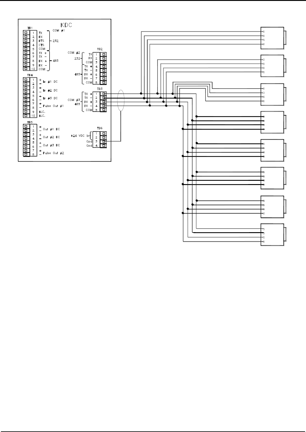
Section IV – Diagrams
64 MN06140 Issue/Rev. 0.6 (8/15)
Figure 57. EIA-485 (Four-Wire) Additive Communication (Lubrizol Blend-Pak) (One Board Set)
Caution: Each board set should be handled individually and contains its own “unique” 24v DC power supply. All
external devices such as pulse transmitters, RTD’s, 4-20mA devices and communication wiring that interface with a
board set MUST be powered by the +24VDC supplied by that board set and all the grounds including shield wires
must be connected/isolated to that board set, including the associated +24VDC distribution block. A sharing of power
supplies and grounding between board sets can cause ground loops leading to communication problems, external
device issues and instability of the DC power supply output from the EAAI board.
Tx
Rx
Tx
Rx
+
-
+
-
Tx
-
Rx
Tx +
-
Rx +
Tx
Tx
-
Rx
Tx +
-
Rx +
-
Rx
Tx +
Rx +
-
Tx
Tx
-
Rx
Tx +
-
Rx +
-
+Tx
Rx
Tx +
Rx +
-
Tx
-
+Rx
Rx-
Tx
-
Tx
Rx
+
-
Rx +
Blend Pak
Additive Systems
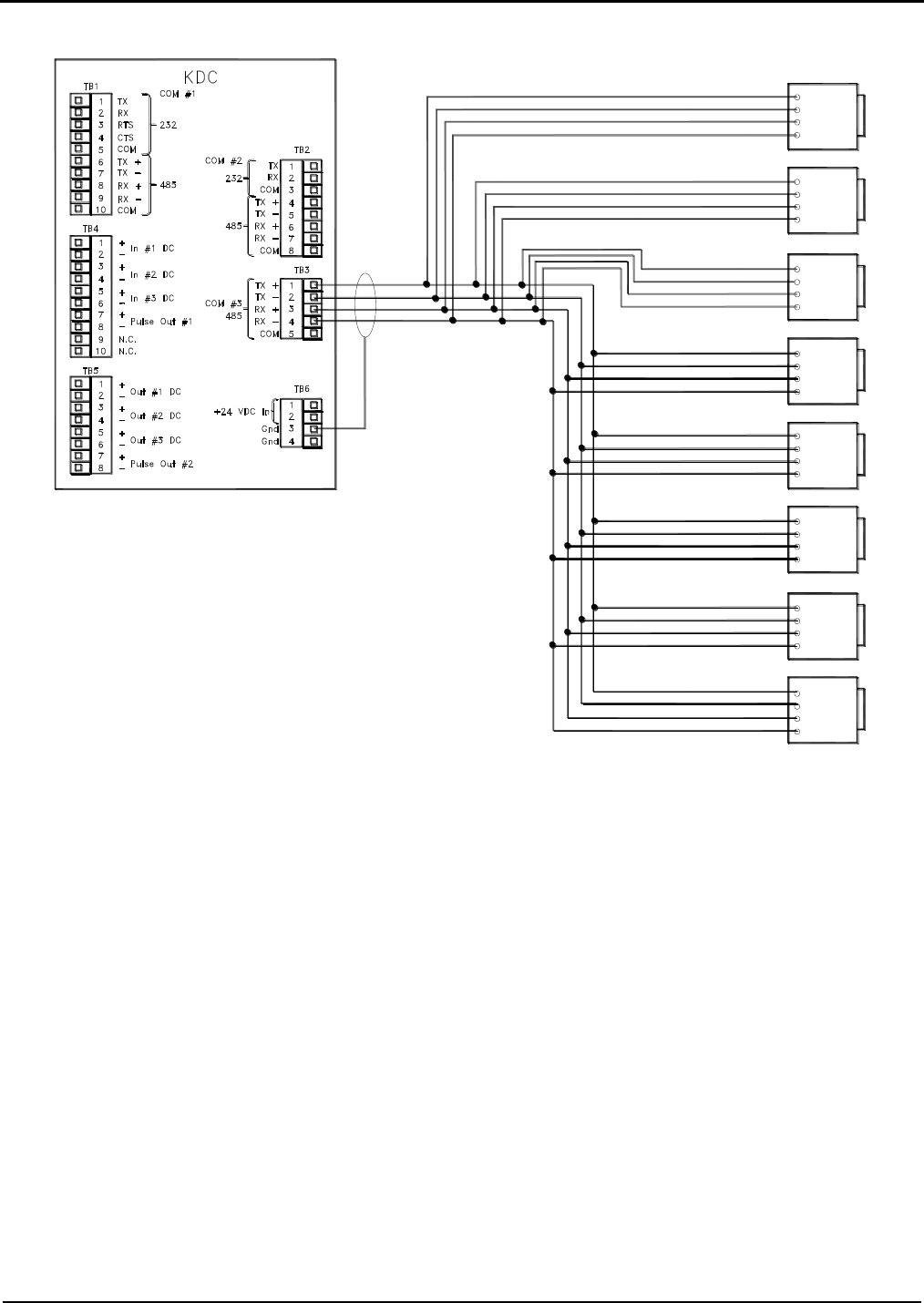
Section IV – Diagrams
MN06140 Issue/Rev. 0.6 (8/15) 65
Figure 58. EIA-485 (Four-Wire) Additive Communication (Titan Pac3) (One Board Set)
Caution: Each board set should be handled individually and contains its own “unique” 24v DC power supply. All
external devices such as pulse transmitters, RTD’s, 4-20mA devices and communication wiring that interface with a
board set MUST be powered by the +24VDC supplied by that board set and all the grounds including shield wires
must be connected/isolated to that board set, including the associated +24VDC distribution block. A sharing of power
supplies and grounding between board sets can cause ground loops leading to communication problems, external
device issues and instability of the DC power supply output from the EAAI board.
Tx
Rx
Additive Systems
Tx
Rx
+
-
+
-
Tx
-
Rx
Tx +
-
Rx +
Tx
Tx
-
Rx
Tx +
-
Rx +
-
Rx
Tx +
Rx +
-
Tx
Tx
-
Rx
Tx +
-
Rx +
-
+Tx
Rx
Tx +
Rx +
-
Tx
-
+Rx
Rx-
Tx
-
Tx
Rx
+
-
Rx +
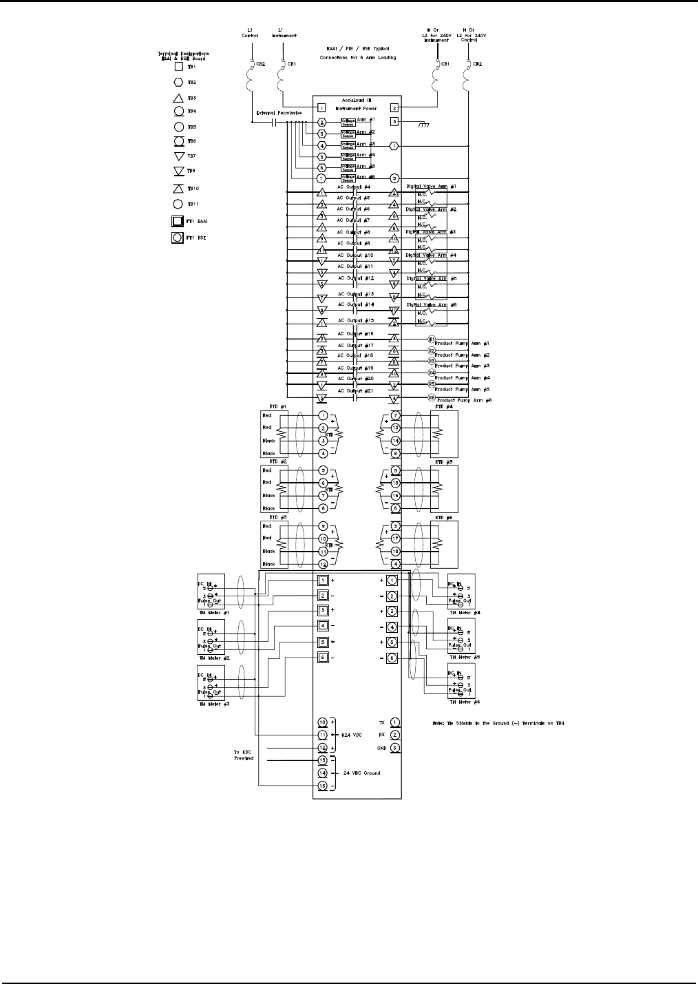
Section IV – Diagrams
66 MN06140 Issue/Rev. 0.6 (8/15)
Figure 59. Typical Six-Arm Straight Product Loading (One Board Set)
Caution: Each board set should be handled individually and contains its own “unique” 24v DC power supply. All
external devices such as pulse transmitters, RTD’s, 4-20mA devices and communication wiring that interface with a
board set MUST be powered by the +24VDC supplied by that board set and all the grounds including shield wires
must be connected/isolated to that board set, including the associated +24VDC distribution block. A sharing of power
supplies and grounding between board sets can cause ground loops leading to communication problems, external
device issues and instability of the DC power supply output from the EAAI board.
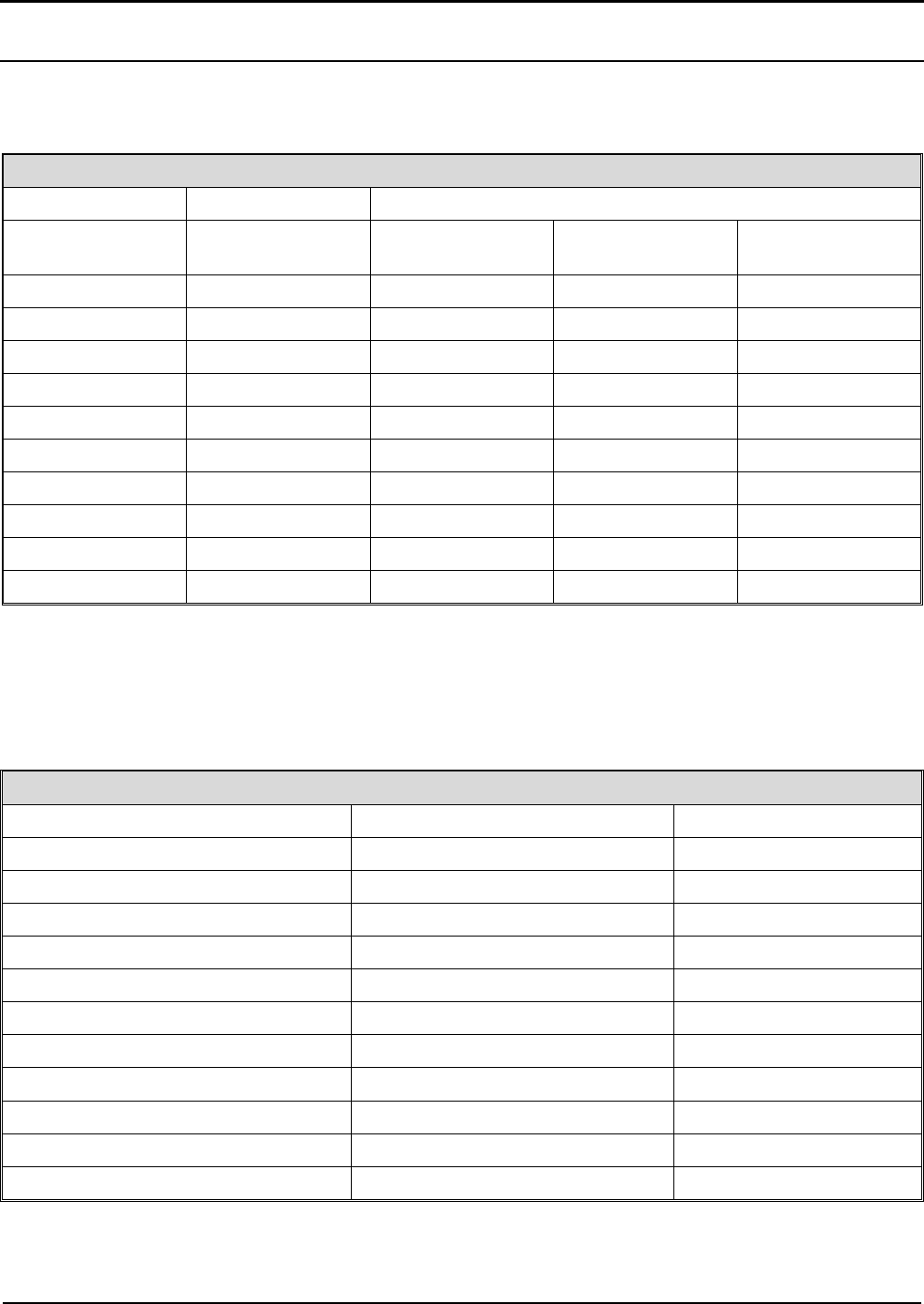
Section IV – Diagrams
MN06140 Issue/Rev. 0.6 (8/15) 67
Optional AICB Board (Additive Inputs/Outputs) (Per Board Set)
Terminal connections for the optional AICB board are shown in Figure . Metered Additive Pulses 1 through 4
are wired into the PIB board on the EAAI board. Metered Additives 5 through 24 are wired to the AICB board(s).
Connections are shown in the table below.
Meter Pulses (Optional AICB)
Injector #
Metered Additive Pulses
ALIII-SA
Hardware
Terminal Block
+ Voltage
Signal
Common
5
TB5
1
2
3
6
TB5
4
5
6
7
TB5, TB4
7 (TB5)
8 (TB5)
1 (TB4)
8
TB4
2
3
4
9
TB4
5
6
7
10
TB4
8
9
10
11
TB3
1
2
3
12
TB3
4
5
6
13
TB3
7
8
9
14
TB3
10
11
12
Table 16. Meter Pulses
Additive Pumps 1 through 4 are wired to the programmed terminals on the EAAI board. Additive Pumps 5 through
24 are wired per the following table. Terminals are automatically assigned as additive pumps if metered injectors
are programmed in the AccuLoad.
Additive Pumps (Optional AICB)
Additive Pump #
ALIII-SA Hardware
Terminal +V
Terminal Block
5
10
TB8
6
8
TB8
7
6
TB8
8
4
TB8
9
2
TB8
10
10
TB7
11
8
TB7
12
6
TB7
13
4
TB7
14
2
TB7
Table 17. Additive Pumps

Section IV – Diagrams
68 MN06140 Issue/Rev. 0.6 (8/15)
Additive Solenoids 1 through 4 are wired to the programmed terminals on the EAAI board. Additive Solenoids 5
through 24 are wired per the following table. Terminals are automatically assigned as additive solenoids if
metered injectors are programmed in the AccuLoad.
Additive Solenoids (Optional AICB)
Additive Solenoid #
ALIII-SA Hardware
Terminal +V
Terminal Block
5
9
TB8
6
7
TB8
7
5
TB8
8
3
TB8
9
1
TB8
10
9
TB7
11
7
TB7
12
5
TB7
13
3
TB7
14
1
TB7
Table 18. Additive Solenoids
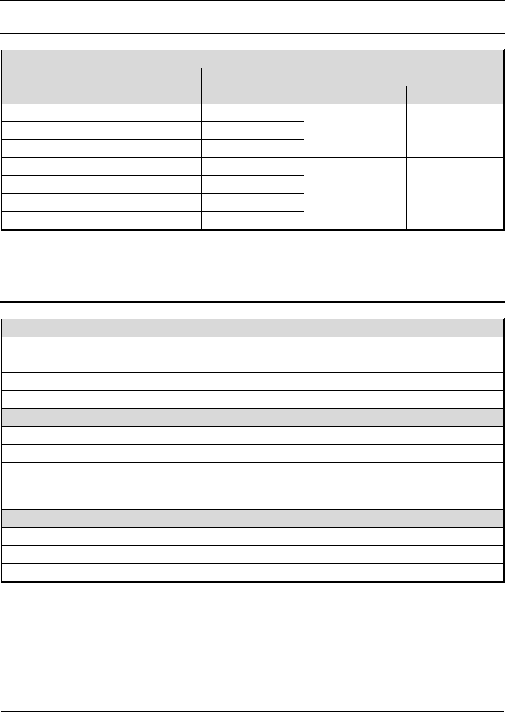
Section IV – Diagrams
MN06140 Issue/Rev. 0.6 (8/15) 69
Communications (AICB Boards)
Communications
Type
Function
Terminal
Jumpers
CN4
CN5
EIA - 232
TX
TB2 (4)
1-2 Out
3-4 Out
5-6 In
1-2 Out
3-4 Out
EIA – 232
RX
TB2 (2)
EIA – 232
Com
TB1 (2)
EIA - 485
RX+
TB2 (1)
1-2 Out
3-4 Out
5-6 Out
1-2 In
3-4 In
EIA - 485
RX-
TB2 (2)
EIA - 485
TX+
TB2 (3)
EIA - 485
TX-
TB2 (4)
Table 19. Communications
Jumper Locations (AICB Board)
Transmitter Power
Designation
Jumpers
Factory Default
Description
CN2
1 – 2
In
24V – +V Out
CN2
3 – 4
Out
12V – +V Out
CN2
5 – 6
In
5V – +V Out
Communications
Address
Jumpers
Factory Default
Communications
CN4
1 – 2
Out
In Address 200, Out Address 100*
CN4
3 – 4
Out
In 9600 Baud, Out 38.4K Baud
CN4
5 – 6
In
In 232 Communications,
Out 485 Communications
Last Unit Only (Termination of Communications with AccuLoad)
Address
Jumpers
Factory Default
Communications
CN5
1 – 2
Out
In EIA 485, Out EIA 232
CN5
3 – 4
Out
In EIA 485, Out EIA 232
Table 20 Jumper Locations
*Note: For Additives 5 through 14 on the ALIII-SA hardware, jumper must be out (Address 100), 15 through 24 Address 200.
Note: Jumpers CN1 and CN3 for factory use only.
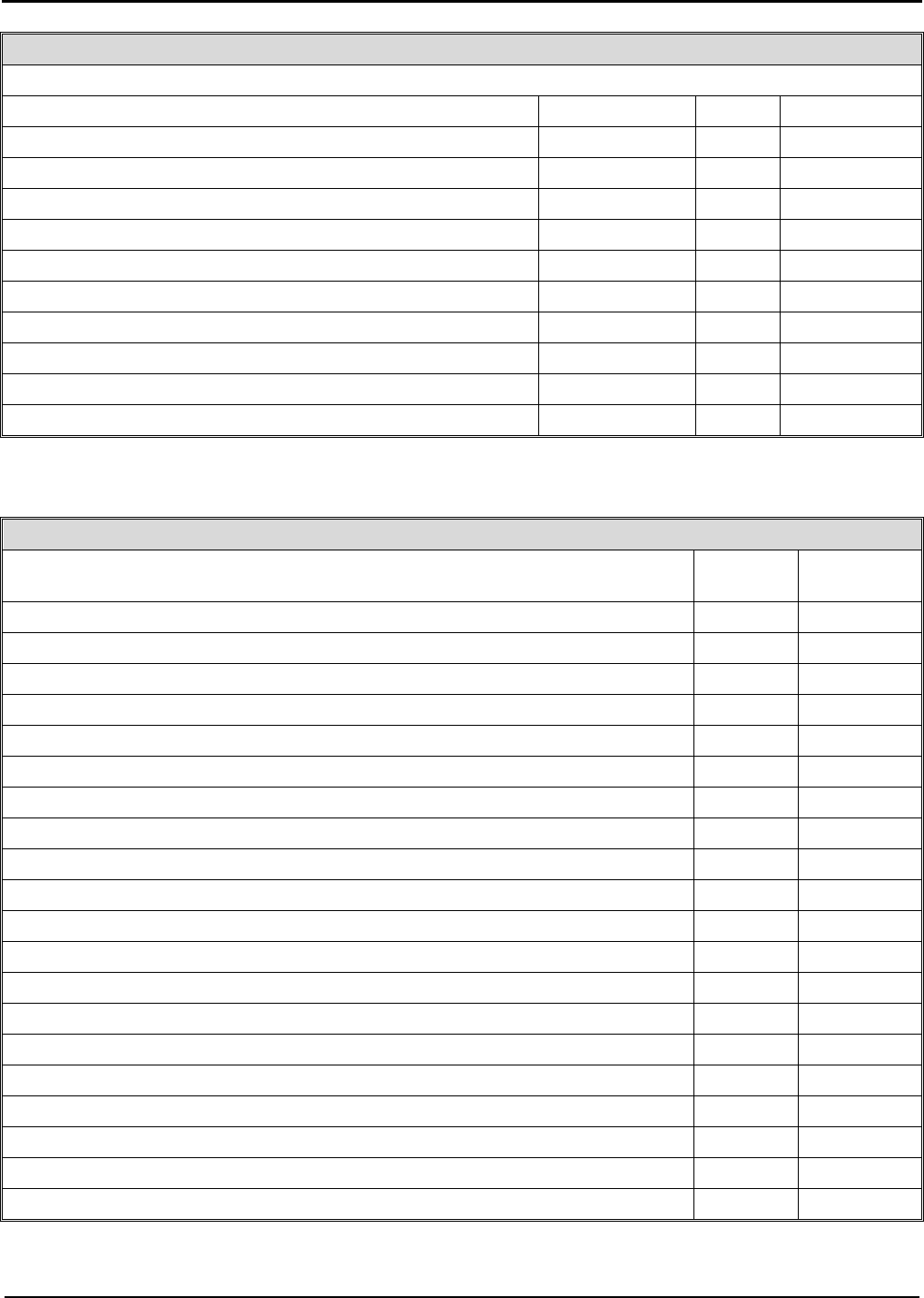
Section IV – Diagrams
70 MN06140 Issue/Rev. 0.6 (8/15)
Optional AICB Board (General Purpose Inputs/Outputs)
DC Inputs (Optional AICB)
Input #
Terminal Block
Signal
Common
24
TB5
2
3
25
TB5
5
6
26
TB5/TB4
8 (TB5)
1 (TB4)
27
TB4
3
4
28
TB4
6
7
29
TB4
9
10
30
TB3
2
3
31
TB3
5
6
32
TB3
8
9
33
TB3
11
12
Table 21. Optional AICB Board
AC Outputs (Optional AICB Board)
Output #
Terminal
+V
Terminal
Block
39
10
TB8
40
9
TB8
41
8
TB8
42
7
TB8
43
6
TB8
44
5
TB8
45
4
TB8
46
3
TB8
47
2
TB8
48
1
TB8
49
10
TB7
50
9
TB7
51
8
TB7
52
7
TB7
53
6
TB7
54
5
TB7
55
4
TB7
56
3
TB7
57
2
TB7
58
1
TB7
Table 22. AC Outputs
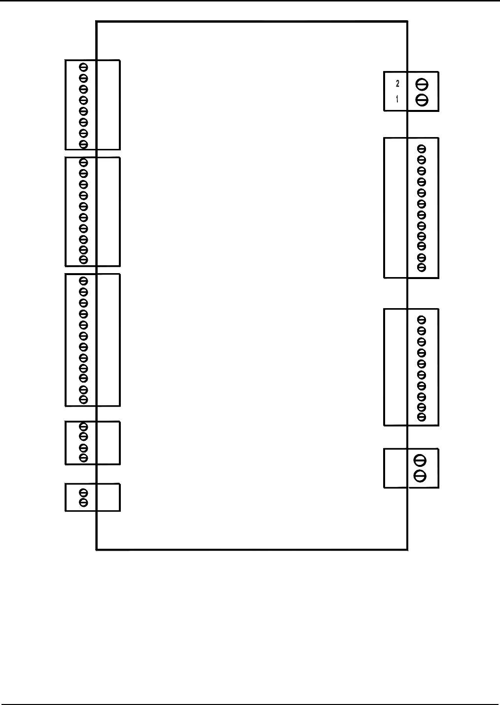
Section IV – Diagrams
MN06140 Issue/Rev. 0.6 (8/15) 71
Figure 60. Optional AICB Board
+ V Out
DC IN #1 Signal
Common
DC IN #2 Signal
Common
+ V Out
DC IN #3 Signal
+ V Out
1
2
3
4
7
8
5
6
7
8
3
5
6
4
1
2
+ V Out
DC IN #5 Signal
DC IN #4 Signal
Common
+ V Out
Common
9
10
DC IN #6 Signal
Common
+ V Out
Common
7
9
10
8
3
5
6
4
1
2
11
12
Common
DC IN #9 Signal
+ V Out
Common
DC IN #8 Signal
DC IN #7 Signal
+ V Out
Common
+ V Out
DC IN #10 Signal
Common
+ V Out
4
2
3
1
RS-485 (Tx +)
RS485 (Rx +)
RS-485 (RX -)/RS232 (Rx)
RS-485 (Tx -)/RS232 (Tx)
1
2
+24 VDC
Common
AC L1 Input
To Out 1 - Out 10
1
2
4
3
7
8
6
5
9
10
12
11
N/C
N/C
Out 1
Out 2
Out 4
Out 3
Out 6
Out 8
Out 7
Out 5
Out 9
Out 10
5
1
3
2
4
10
9
7
6
8
Out 16
Out 20
Out 19
Out 18
Out 17
Out 12
Out 15
Out 14
Out 13
Out 11
2
1
AC L1 Input
To Out 11-Out 20
AICB Board
TB5
TB4
TB3
TB2
TB1
TB6
TB7
TB8
TB9
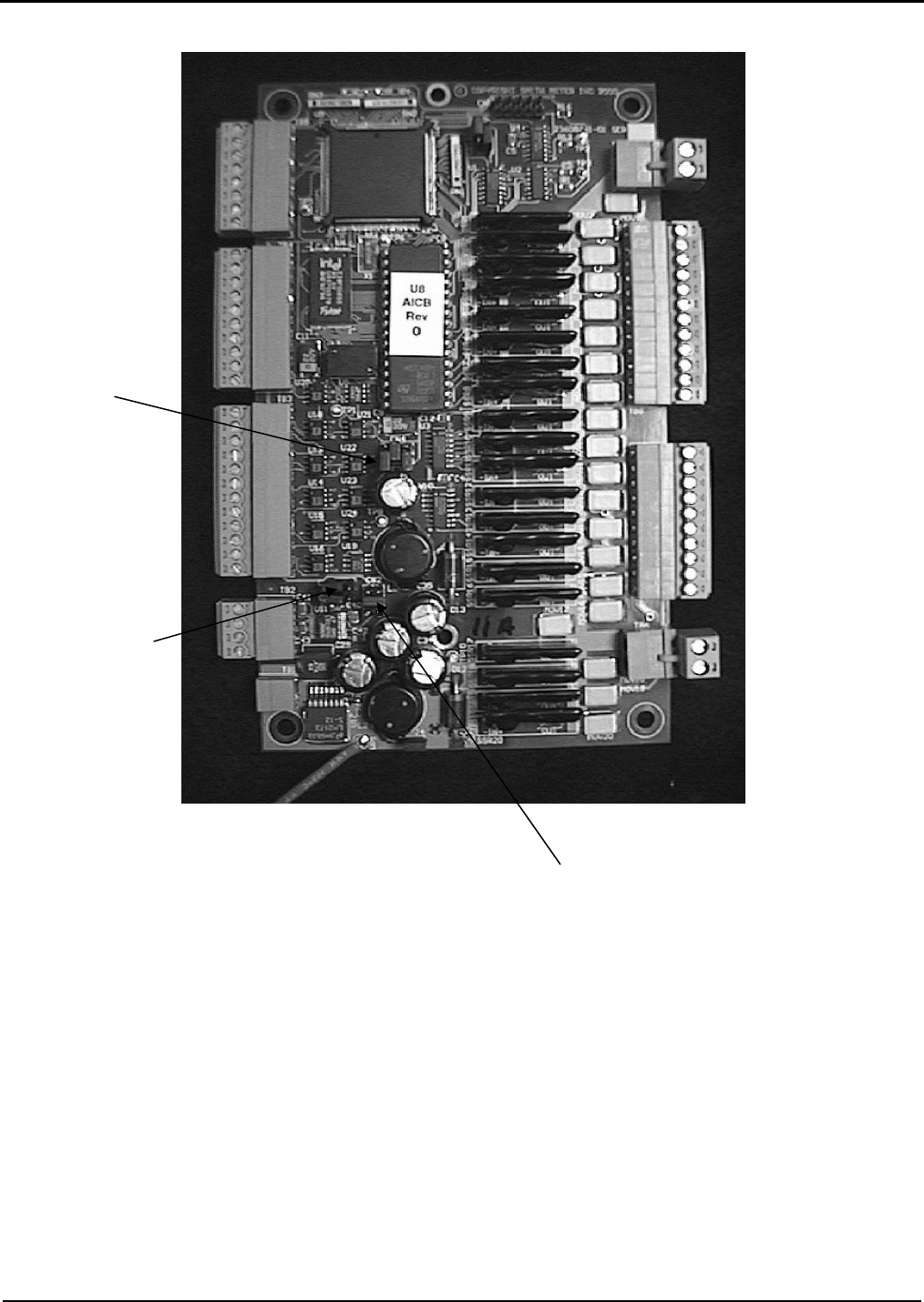
Section IV – Diagrams
72 MN06140 Issue/Rev. 0.6 (8/15)
Figure 61. AICB Jumper Locations
Jumpers CN4
Jumpers CN5
Jumpers CN2
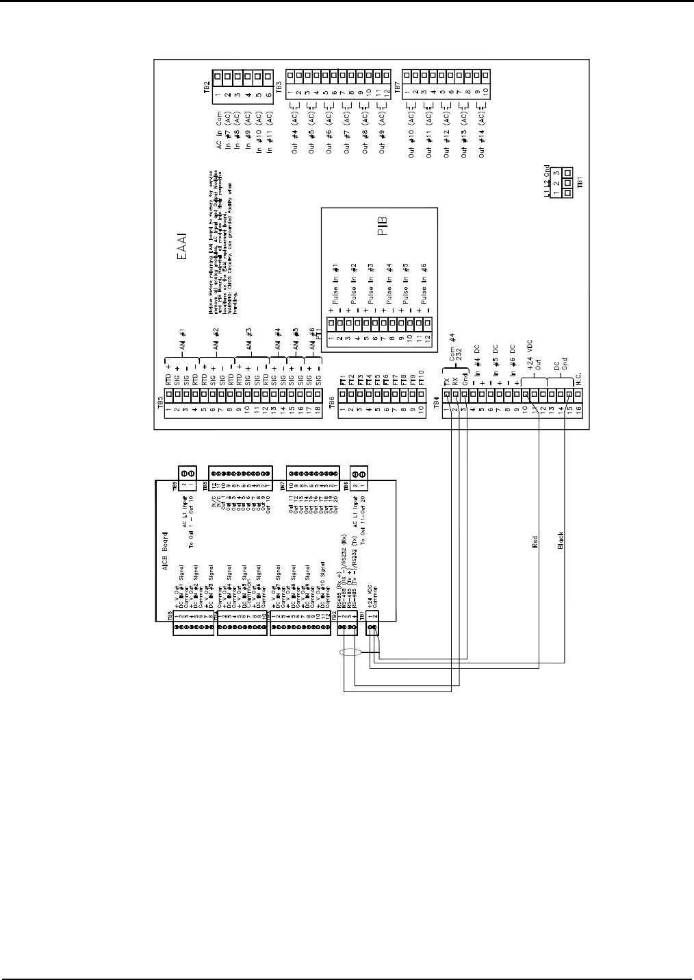
Section IV – Diagrams
MN06140 Issue/Rev. 0.6 (8/15) 73
Figure 62. AICB Communications and DC Power
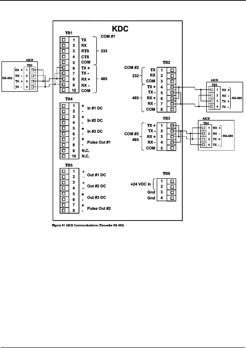
Section IV – Diagrams
74 MN06140 Issue/Rev. 0.6 (8/15)
Figure 63. AICB Communications (Two-wire RS-485)
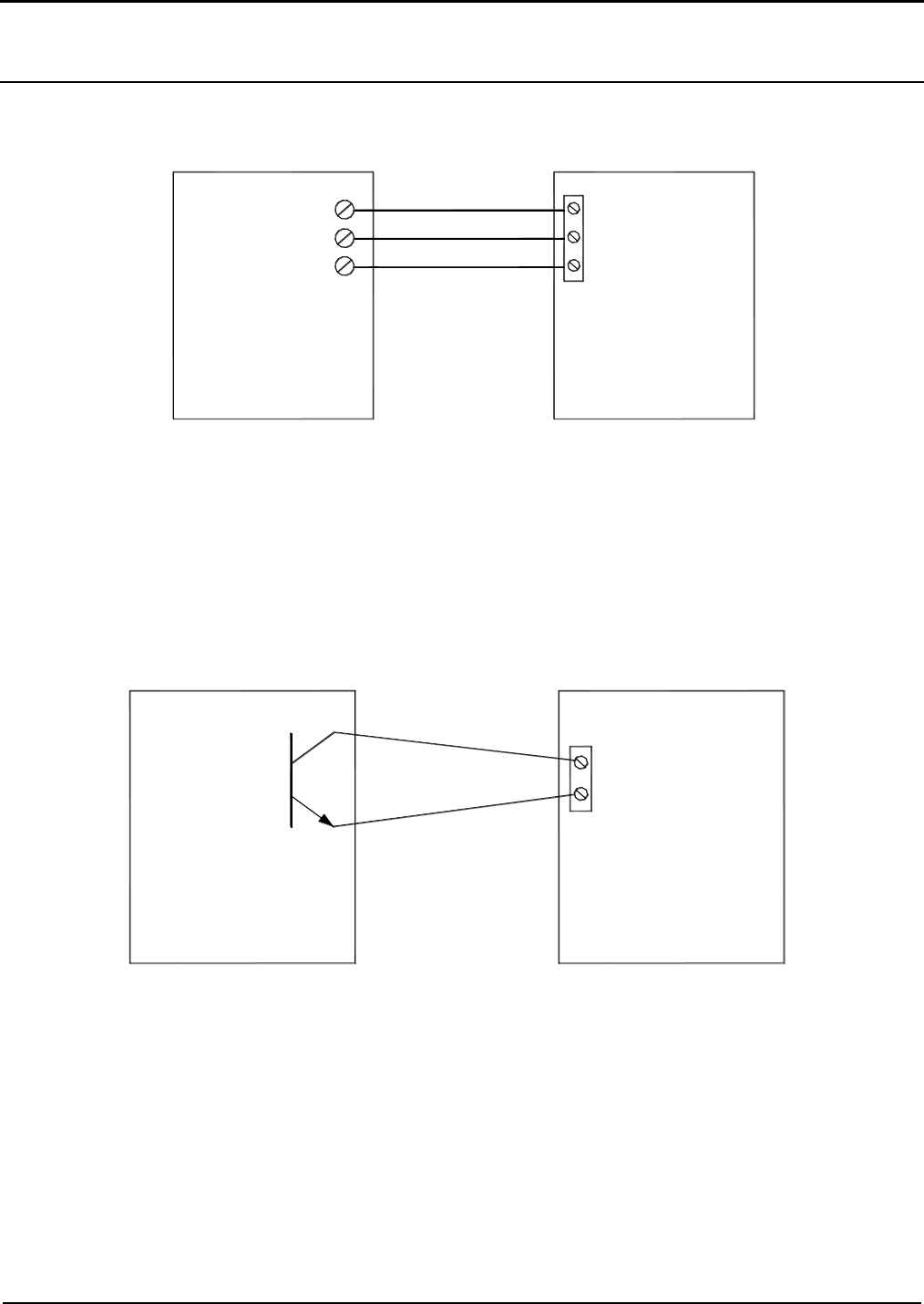
Section IV – Diagrams
MN06140 Issue/Rev. 0.6 (8/15) 75
Digital Inputs – AICB
Figure 64. Metered Injector / Pulse Transmitter Wiring Diagram
Caution: For clarity, shields not shown. Connect shields to Terminals 3, 13, 14, or 15 of Terminal Block 4.
Figure 65. Metered Injector / Open Collector Wiring Diagram
Caution: For clarity, shields not shown. Connect shields to Terminals 3, 13, 14, or 15 of Terminal Block 4.
METERED INJECTOR
OR
PULSE TRANSMITTER
AICB
+V
SIG
COMM
V+ (SELECTABLE)
SIG
COMM
Monoblock Additive Meter
METERED INJECTOR
OR
PULSE TRANSMITTER
AICB
SIG
COMM
Monoblock Additive Meter
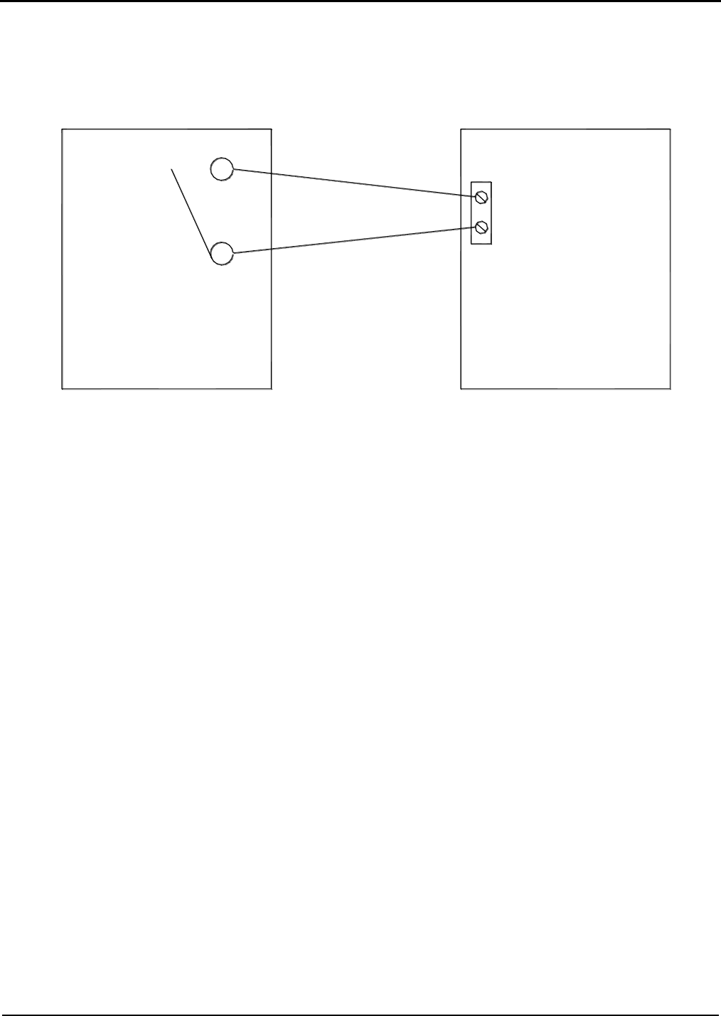
Section IV – Diagrams
76 MN06140 Issue/Rev. 0.6 (8/15)
Figure 66. Metered Injector / Contact Closure Wiring Diagram
Caution: For clarity, shields not shown. Connect shields to Terminals 3, 13, 14, or 15 of Terminal Block 4.
METERED INJECTOR
OR
PULSE TRANSMITTER
AICB
SIG
COMM
Monoblock Additive Meter
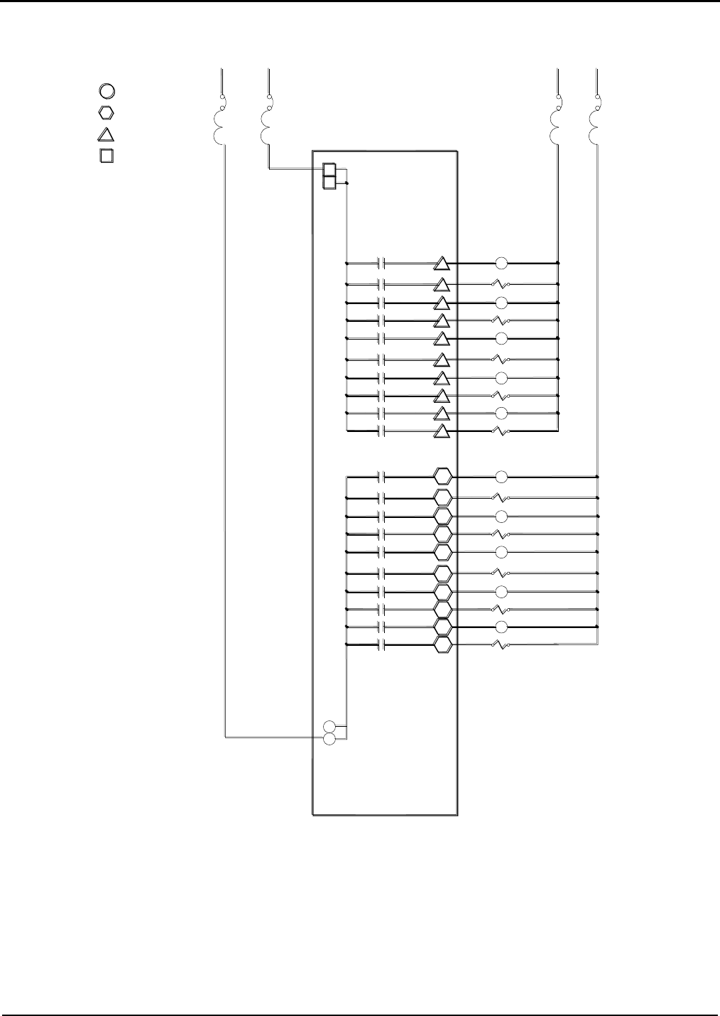
Section IV – Diagrams
MN06140 Issue/Rev. 0.6 (8/15) 77
Figure 67. AICB Additive Outputs
Note: ALIII-SA Hardware Additive Pumps start at 5 and go through 14, as do the additive solenoid
2
9
8
7
Add. Sol. 6
Add. Sol. 5
AC Output #2
AC Output #3
AC Output #4
CB2 CB2
TB9
TB7
TB8
TB6
AICB
Terminal Designations
AICB Connections
L1
L2 for 240V
N Or
Control
Add. Pump 6
AC Output #1
10
Add. Pump 5
AC Output #5
AC Output #8
AC Output #7
AC Output #6
4
3
5
6
Add. Sol. 8
Add. Pump 8
Add. Pump 7
Add. Sol. 7
AC Output #10
1
AC Output #9
2
Add. Sol. 9
Add. Pump 9
1
AC Output #20
AC Output #19
AC Output #18
1
2
3
AC Output #17
AC Output #16
AC Output #15
AC Output #14
AC Output #13
AC Output #12
AC Output #11
8
4
5
6
7
9
10
Add. Sol. 14
Add. Pump 14
Add. Sol. 13
Add. Pump 12
Add. Pump 13
Add. Sol. 11
Add. Sol. 12
Add. Pump 11
Add. Pump 10
Add. Sol. 10
2
1
CB1 CB1
Control
L2 for 240V
L1
N Or

Section V – Specifications
78 MN06140 Issue/Rev. 0.6 (8/15)
Specifications (AccuLoad III)
Accuracy
Calculated Accuracy: The gross at standard tem-
perature and pressure to gross volume ratio, ex-
cluding the accuracy of fluid temperature meas-
urement, will exactly match the proper volume cor-
rection factor of ASTM-D-1250 (May 2004) over
the fluid temperature range of -40°F to 572°F (-
40°C to 300°C).
Temperature Measurement Accuracy: Fluid tempera-
ture is measured to within ±0.72°F (±0.4°C) over the
fluid temperature range of -148°F to 572°F
(-100°C to 300°C). Fluid temperature is measured
to within ±0.45°F (±0.25°C) over the fluid tempera-
ture range of 32°F to 572°F (0°C to 300°C).
Stability: 0.1°F (0.06°C)/year.
Flow Totalizing: Within one pulse of input frequency.
Weight
AccuLoad III-MMI: Approximately 35 lb (15.90 kg).
AccuLoad III-FCM: Approximately 120 lb (54.54 kg).
Electrical Inputs (Per Board Set)
AC Instrument Power:
Universal input 100 to 240 Vac, 58W maximum,
48 to 63 Hz. The AC circuitry is fuse-protected.
Surge Current: 28A maximum for less than 0.1
seconds.
Power Interruption Tolerance: Interruption of
power greater than .05 seconds (typical) will
cause an orderly shut-down of the AccuLoad and
the control valve will be immediately signaled to
close.
Note: A constant voltage transformer (CVT) is recommended
if the available AC power is suspected not to comply with
these specifications.
Pulse Input:
Type: High-speed, edge-triggered, optically iso-
lated pulse transmitter input. The input pulse must
rise above V (high min.) for a period of time and
then fall below V (low) to be recognized as a
pulse by AccuLoad III.
V (High): 5 Vdc minimum to 28 Vdc maximum.
V (Low): 1 Vdc maximum.
Input Impedance: 1.8 KΩ
Pulse Resolution: 1 pulse/unit minimum, 9,999
pulses/unit maximum.
Frequency Range: 0 to 10.0 kHz.
Response: Within one pulse to a step change in
flow rate.
Mode: Single, dual, dual with power sensing,
density.
Duty Cycle: 35/65 to 65/35 (on/off).
Temperature Probe:
Type: Four-wire, 100 Ω Platinum Resistance
Temperature Detector (PRTD).
Temperature Coefficient: @ 32°F: 0.00214
Ω/Ω/°F (0.00385 Ω/Ω/°C).
Temperature Range: -148°F to 572°F (-100°C to
300°C).
Offset: Temperature probe offset is program-
adjustable through the AccuLoad keypad in ±0.1
degree increments in the unit of temperature
measurement used.
Self-calibrating: Lead length compensation that
requires no resistance balancing of leads.
Analog (4-20mA):
Type: Two-wire, 4-20mA current loop receiver, iso-
lated from ground, programmable as to function.
Span Adjustment: Program-adjustable through
the AccuLoad keypad or communication in tenths
of the unit used.
Input Burden: 50 Ω.
Accuracy: ±0.025% of range.
Resolution: One part in 65,536.
Voltage Drop: 2 Volts maximum.
Sampling Rate: One sample/300 mSec minimum.
Analog (1-5 Vdc):
Type: Two-wire, 1-5 Vdc voltage loop receiver,
isolated from ground, programmable as to func-
tion.
Span Adjustment: Program-adjustable through
the AccuLoad keypad or communications in
tenths of the unit used.
Input Burden: 1 m Ω
Accuracy: ±0.025% of range
Resolution: One part in 65,536.
Sampling Rate: One sample/300 mSec minimum.
AC Inputs:
Type: Optically-isolated, solid-state voltage sensor.
Input Voltage Range: 90 to 280 Vac.
Pickup Voltage: 90 Vac minimum.
Drop-out Voltage: 30 Vac maximum.
Current at Maximum Voltage: 20mA maximum.
Input Resistance: 44,000 Ω typical.

Section V – Specifications
MN06140 Issue/Rev. 0.6 (8/15) 79
DC Inputs:
Type: Optically-isolated solid state voltage sensors
Input Voltage Range: 5 to 28 Vdc.
Pickup Voltage: 5 Vdc minimum.
Drop-out Voltage: Less than 1 volt.
Current at Maximum Voltage: 20mA maximum.
Input Level Duration: 120 mSec minimum.
Keypad:
Type: Metal encapsulated, one-piece, sealed, no
moving parts, piezoelectric design. Protected
against the environment.
Display:
The Graphics Display is a 240 by 64 pixel graphic
Liquid Crystal Display (LCD) modules with LED
back-lighting.
Electrical Outputs (Per Board Set)
DC Power:
24 Vdc ±10%, 1 A maximum, short circuit protected.
AC Outputs:
Type: Optically-isolated, AC, solid-state relays.
User-programmable as to function.
Load Voltage Range: 90 to 280 Vac (rms), 48 to
63 Hz.
Steady-State Load Current Range: 0.05A (rms)
minimum to 1.0A (rms) maximum into an
inductive load.
Leakage Current at Maximum Voltage Rating:
5.2mA (rms) maximum @ 240 Vac.
On-State Voltage Drop: 2 Vac at maximum load.
DC Outputs:
Type: Optically-isolated solid state output. User-
programmable as to function.
Polarity: Programmable (normally open or
normally closed).*
Switch Blocking Voltage: 30 Vdc maximum.
Load Current: 150mA maximum with 0.6 volt
drop.
Note: *Power-down normally open.
Analog (4-20mA):
Type: Two-wire, 4-20mA current loop transmitter,
isolated from ground, programmable as to function.
Span Adjustment: Program adjustable through the
AccuLoad keypad or through communications.
Accuracy: ±0.025% of range.
Resolution: One part in 65,536.
Voltage Burden: 4 volts maximum.
Analog (1-5 Vdc):
Type: Two-wire, 1-5 Vdc voltage loop transmitter,
isolated from ground, programmable as to function.
Span Adjustment: Program adjustable through the
AccuLoad keypad or through communications.
Accuracy: ±0.025% of range.
Resolution: One part in 65,536.
Pulse Output:
Type: Optically-isolated solid state output. Pulser
output units are program-selectable through the
AccuLoad keypad or communications.
Polarity: Programmable (normally open or normal-
ly closed).
Switch Blocking Voltage (Switch Off): 30 Vdc
maximum.
Load Current (Switch On): 10mA with 0.6 volts
drop.
Frequency Range: 0 to 3000 Hz.
Duty Cycle: 50/50 (on/off).
Environment
Ambient Operating Temperature
-40F to 140F (-40C to 60C).
Humidity:
5 to 95% with condensation.
Enclosure:
Industrial type 4X.

Section V – Specifications
80 MN06140 Issue/Rev. 0.6 (8/15)
Approvals
UL/CUL
Class I, Division 2, Groups C & D; UNL-UL Enclo-
sure 4X, CNL-CSA Enclosure 4.
Class I, Zone 2, Group IIB.
UL/CUL File E23545 (N).
Notes: The Standard AccuLoad III does not contain intrinsically-
safe circuitry; therefore, all peripheral equipment must be suitable
for the area in which it is installed.
When supplied with the optional Civacon Overfill and Grounding
Board the AccuLoad III does contain intrinsically safe circuitry.
Only the equipment connected to the circuitry is intrinsically safe.
Communications (Per Board Set)
General
Number of Ports: Four.
Configuration: Multi-drop network.
Data Rate: Keypad-selectable to asynchronous da-
ta rates of 1,200, 2,400, 3,600, 4,800, 7,200,
9,600, 19,200, or 38,400 bps.
Data Format: Programmable one start bit, pro-
grammable seven or eight data bits - even, odd, or
no parity, one stop bit.
Line Protocol: Half-duplex, full-duplex, no character
echo.
Data Structure: ASCII character-oriented, modeled
after ISO Standard 1155.
Protocol: Smith ASCII LRC, Smith ASCII CR,
Smith ASCII binary, Modbus.
AccuLoad II Style: Terminal Mode, Minicomputer
Mode.
EIA-232 (1 dedicated, 2 selectable)
Type: Interfaceable with EIA-232 data communica-
tion standards. Data transmitters are tri-state de-
sign.
Typical Applications: Product receipt ticket printing
(used with a stand-alone ASCII printer or as a
backup in the standby mode with automation for
BOL emulation) or communications with Product
Management Automation Systems. Up to 16 Accu-
Loads can be connected onto the same transmit
and receive data lines.
EIA-485 (1 dedicated, 2 selectable)
Type: Interfaceable with EIA-485 data communica-
tion standards.
Typical Application: Communications with Product
Management Automation Systems.
Number of Units per Communication Line: Up to 32
AccuLoads can be connected onto the same
transmit and receive data lines.
Specifications (AICB Board - Optional)
Electrical Inputs
DC Instrument Power:
24 Vdc ±10%, 1 watt maximum
Pulse Input:
Type: High-speed, edge-triggered, optically iso-
lated, compatible with contact closure, open col-
lector or voltage sink/source pulse transmitter in-
put. The input pulse must rise above V (high min.)
for a period of time and then fall below V (low) to
be recognized as a pulse.
V (High): 10 Vdc minimum to 24 Vdc maximum.
V (Low): 8 Vdc maximum.
Pulse Resolution: 1 pulse/unit minimum, 9,999
pulses/unit maximum.
Frequency Range: 0 to 5 kHz.
Response: Within one pulse to a step change in
flow rate.
Minimum Pulse Width: 50 uS.
Electrical Outputs
AC Outputs:
Type: Optically-isolated, AC, solid-state relays.
User-programmable by the host as to function.
Load Voltage Range: 90 to 275 Vac (rms), 48 to
63 Hz.
Steady-State Load Current Range: 0.05A (rms)
minimum to 0.5A (rms) maximum into an induc-
tive load.
Leakage Current at Maximum Voltage Rating:
0.1mA (rms) maximum at 240 Vac.
On-State Voltage Drop: 1.5 Vac at maximum
load.

Section V – Specifications
MN06140 Issue/Rev. 0.6 (8/15) 81
Environment
Ambient Operating Temperature
-40
o
F to 140
o
F (-40
o
C to 60
o
C).
Humidity:
5 to 95% with condensation.
Remote Enclosure:
Explosion-proof (NEMA 7, Class I, Groups C and
D) and watertight (NEMA 4X), IP65
Approvals (Remote Enclosure)
UL/CUL:
Class I, Division 1, Groups C and D; UNL-UL
Enclosure 4X, CNL-CSA Enclosure 4.
Class I, Zone 1, AEx d IIB T6, IP65.
Specifications (Red and Green
Indicating Light Units - Optional)
Electrical Ratings
Bulbs:
LED Lamp, 120V AC in Red or Green
Terminals
Saddle clamp type for 1 x 22 AWG
Specifications (Stop Button - Optional)
Electrical Ratings
Contact Block:
A600 (AC): 120V maximum
Make and Emergency Interrupting Capacity
(Amps): 60 (120V); 30 (240V)
Normal Load Break (Amps): 6 (120V); 3 (240V)
Thermal Current (Amp): 10
Voltamperes: Maximum Make 7200; Maximum
Break 720
Contact Type:
1N0-1NC (Momentary)
Color: Black
Terminals
Stainless steel saddle clamp type for 1 x 18 - 14
AWG (0.75 - 2.5 sq. mm) solid or stranded copper
conductor

Section VI – Related Publications
Printed in U.S.A. © 8/15 FMC Technologies Measurement Solutions, Inc. All rights reserved. MN06140 Issue/Rev. 0.6 (8/15)
The following literature can be obtained from FMC Measurement Solutions Literature Fulfillment at
measurement.fulfillment@fmcti.com or online at www.fmctechnologies.com/measurementsolutions.
When requesting literature from Literature Fulfillment, please reference the appropriate bulletin number and title.
AccuMate for AccuLoad III-SA
Specification .......................................................................................................................... Bulletin SS06032
Installation/Operation ............................................................................................................. Bulletin MN06136
AccuLoad III-SA
Specification .......................................................................................................................... Bulletin SS06039
Operator Reference ............................................................................................................... Bulletin MN06139
AccuLoad III-X
Communications .................................................................................................................... Bulletin MN06130L
Modbus Communications ..................................................................................................... Bulletin MN06131L
Revisions included in MN06140 Issue/Rev. 0.6 (8/15):
Page 3: Updated Pre-Installation Considerations Section: See "Important Electrical Safety Installation Notes.
