
1
Standard Instructions
For
MC-2000/3000/4000
Controllers
Manual Update: 09/12/11
Version: 3.10

2
1 QUICK REFERENCE GUIDE
1.1 NAVIGATING THE DISPLAY
Interacting with the AboveAir Technologies unit is accomplished through the Carel pGD user interface.
This wall- or unit-mounted display terminal allows access to all of the unit features.
The home screen will show the current temperature sensed by the unit identifier (if connected to BMS),
date, time, temperature, and unit status. A flashing cursor will be displayed in the upper left corner of
the screen.
Press the PRG key to access the menu system. Use the up (↑
↑↑
↑) and down (↓
↓↓
↓) arrows to scroll through the
available menus. The current menu selection will be highlighted: > CURRENT SELECTION <. To access a
menu, press the enter (↵
↵↵
↵) key once.
Pressing ↑
↑↑
↑ or ↓
↓↓
↓ while the cursor is in the upper left corner of the screen will scroll through the available
submenus within the current selection. To leave a menu, press ESC. To return to the screen, press ESC
once more.
To choose an adjustable parameter, press ↵
↵↵
↵ once. The cursor will move from the top left corner of the
display to the first user adjustable data field. Press ↵
↵↵
↵ again to select the next user adjustable data field.
After using ↵
↵↵
↵ to cycle through all user adjustable data fields on the current screen, the cursor will move
back to the top left corner of the display.
To change an adjustable data field, press ↵
↵↵
↵ until the flashing cursor is positioned on the desired field.
Press ↑
↑↑
↑ or ↓
↓↓
↓ to change the selection. Press ↵
↵↵
↵ again to confirm the selection.
1.2 SYSTEM ALARMS
If the system enters into an alarm condition, an alarm will sound from the display terminal and the
alarm key will illuminate. To silence the alarm, press the alarm key. The system display will change to
show the date, time, and nature of the current alarm.
1.3 START-UP REFERENCES
The following sections should be referenced while performing system start-up procedures:
Procedure
Section
To activate system/components
3.3 Enables
To adjust setpoints
3.4 Setpoints
To manually run components
4.5 Manual Control
To set up pLan networks
6 pLan Network Setup
To set up BMS options
7 BMS Setup
3
1. Contents
1 QUICK REFERENCE GUIDE ................................................................................................................ 2
1.1 NAVIGATING THE DISPLAY ........................................................................................................ 2
1.2 SYSTEM ALARMS ...................................................................................................................... 2
1.3 START-UP REFERENCES ............................................................................................................ 2
2 GENERAL INFORMATION ................................................................................................................. 6
2.1 INTRODUCTION ........................................................................................................................ 6
2.2 APPLICATIONS .......................................................................................................................... 6
2.3 STANDARD FUNCTIONS ............................................................................................................ 6
2.4 MAIN CONTROL BOARD ........................................................................................................... 6
2.5 DISPLAY TERMINAL .................................................................................................................. 6
2.5.1 CHANGING THE TERMINAL ADDRESS ................................................................................ 7
2.5.2 ADJUSTING THE DISPLAY CONTRAST ................................................................................. 8
2.5.3 SYSTEM INFORMATION .................................................................................................... 8
2.6 SECURITY LEVELS ...................................................................................................................... 8
3 NAVIGATING THE MAIN MENU (LEVEL 1) ......................................................................................... 9
3.1 INTRODUCTION ........................................................................................................................ 9
3.2 SYSTEM STATUS ....................................................................................................................... 9
3.2.1 UNOCCUPIED MODE OVERRIDE ........................................................................................ 9
3.2.2 SYSTEM STATUS AND MODE ........................................................................................... 10
3.3 ENABLES ................................................................................................................................ 10
3.3.1 AFTER AN ALARM ........................................................................................................... 11
3.4 SETPOINTS ............................................................................................................................. 11
3.4.1 STANDARD ..................................................................................................................... 11
3.4.2 MAKEUP AIR/HIGH PERCENTAGE OA .............................................................................. 11
3.4.3 FREECOOL SET POINT ..................................................................................................... 12
3.5 ALARM SET POINTS ................................................................................................................ 12
3.6 RUN HOURS ........................................................................................................................... 12
3.7 DAY MIN/MAX ....................................................................................................................... 12
3.8 ALARM HISTORY ..................................................................................................................... 13
3.9 SET TIME ................................................................................................................................ 13
3.10 SCHEDULE .............................................................................................................................. 13
3.11 UNOCCUPIED CNTRL .............................................................................................................. 13
3.12 BMS SETUP ............................................................................................................................ 14
3.13 CHANGE PASSWORD .............................................................................................................. 14
4 TECHNICIAN'S MENU (LEVEL 2) ...................................................................................................... 15
4.1 INTRODUCTION ...................................................................................................................... 15
4.2 FAN OPERATION..................................................................................................................... 15
4.3 NETWORK SETUP ................................................................................................................... 16
4.4 TEMPERATURE UNITS............................................................................................................. 16
4.5 MANUAL CONTROL ................................................................................................................ 16
4
4.6 SENSORS ................................................................................................................................ 16
4.7 DIGITAL INPUTS ...................................................................................................................... 17
4.8 ECONOMIZER ......................................................................................................................... 17
4.9 ROOM PRESSURE ................................................................................................................... 17
4.10 CHANGE PASSWORDS ............................................................................................................ 17
4.11 ALARM RELAYS ....................................................................................................................... 18
4.12 SOFTWARE VERSION .............................................................................................................. 18
4.12.1 RESETTING THE UNIT ...................................................................................................... 18
5 FACTORY MENU (LEVEL 3).............................................................................................................. 20
5.1 WARNING .............................................................................................................................. 20
5.2 INTRODUCTION ...................................................................................................................... 20
5.3 I/O SETUP............................................................................................................................... 20
5.3.1 SELECT UNIT TYPE ........................................................................................................... 20
5.3.2 SELECT DIG IN ................................................................................................................. 21
5.3.3 INSTALL SENSORS ........................................................................................................... 21
5.3.4 SELECT OUTPUT .............................................................................................................. 22
5.3.5 ANALOG OUTPUTS ......................................................................................................... 22
5.4 T/H CONTROL RAMPS ............................................................................................................ 23
5.4.1 Ramp Control ................................................................................................................. 23
5.4.2 CL/HT RAMP CNTRL ........................................................................................................ 24
5.4.3 HU/DH RAMP CNTRL ...................................................................................................... 25
5.5 COOLING SETUP ..................................................................................................................... 25
5.5.1 COOLING SETUP ............................................................................................................. 25
5.5.2 COMPRESS SETUP ........................................................................................................... 25
5.5.3 COMPRESSORS ............................................................................................................... 26
5.5.4 FREECOOL SETUP ............................................................................................................ 26
5.6 HEATING SETUP ..................................................................................................................... 27
5.6.1 HEAT SETUP.................................................................................................................... 27
5.6.2 HEATER STAGES .............................................................................................................. 28
5.6.3 HEAT STAGE/RAMP ........................................................................................................ 28
5.7 HUMIDITY SETUP ................................................................................................................... 28
5.7.1 HUMIDITY CONTROL....................................................................................................... 29
5.7.2 HUMIDITY CONTROL....................................................................................................... 29
6 pLAN NETWORK SETUP .................................................................................................................. 30
6.1 CONNECTING UNITS ............................................................................................................... 30
6.2 SAMPLE SETUP ....................................................................................................................... 30
6.2.1 INITIAL SETUP ................................................................................................................. 30
6.2.2 MASTER UNIT SETUP (UNIT-1) ........................................................................................ 31
7 BMS Setup ..................................................................................................................................... 33
7.1 pCOWeb Serial Card (Ethernet Connection)............................................................................ 33
7.2 pCONet (RS-485 Connection for BACnet) ............................................................................... 33
7.3 Points Lists ............................................................................................................................. 35
5
8 ALARMS & TROUBLESHOOTING ..................................................................................................... 37
6
2 GENERAL INFORMATION
2.1 INTRODUCTION
Congratulations on your purchase of an AboveAir Technologies product. Your unit has come equipped
with a Carel pCO controller loaded with the latest AboveAir control software. This guide will lead you
through the features and programming of the microprocessor control module installed in your unit.
2.2 APPLICATIONS
Your unit shipped from the AboveAir factory in one of the following configurations:
• MC-2000: Comfort and Mission Critical Units
• MC-3000: Make-Up Air Units
• MC-4000: Variable Air Volume Units
Refer to the system documentation for specific configuration and features.
2.3 STANDARD FUNCTIONS
The full-featured AboveAir controller program is designed for versatility and customizability. Notable
standard features include:
• Three levels of password protection
• Up to four stages of cooling or one proportional cooling valve (floating point or 0-10 Vdc)
• Economizer Modes (Enthalpy or Temperature Only control)
• Compressor Rotation
• Up to four stages of heating or one proportional heating valve (floating point or 0-10 Vdc)
• Dehumidification by cooling/reheat or relay output.
• Humidity control (On/Off or Proportional control)
• Time scheduling (7 day/24 hour) features for Occupied and Unoccupied modes
• Record of running hours for all subsystems
• System alarming, holding the last 150 alarms in memory
2.4 MAIN CONTROL BOARD
The pCO controller contains a 16-bit microprocessor dedicated to the execution of the control program.
It is fitted with quick connect terminals for connection to the various input and output devices which
comprise your AboveAir system. The program and all of the parameters are saved permanently
onboard in FLASH memory to prevent data loss (without requiring battery backup) in the event of a
power failure.
2.5 DISPLAY TERMINAL
A pGD user interface is provided with every MC-2000, MC-3000, or MC-4000 equipped AboveAir Unit,
either unit-mounted or shipped loose for wall-mounting. The display terminal allows the user to setup
and change unit settings, as well as to display alarms and sensor readings. Refer to the following figure
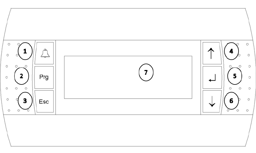
7
for the display terminal layout and a brief description of the buttons; refer to the Quick Reference Guide
(Section 1) for more information on navigating the display.
1. The Alarm (ALRM) key is used to mute a
current alarm and view current/recent
alarms.
2. The Program (PRG) key is used to access
the menu system
3. The Escape (ESC) key is used to exit
selections and menus.
4. The Up Arrow (↑
↑↑
↑) key is used to
navigate menus and change adjustable
values.
5. The Enter (↵
↵↵
↵) key is used to make
selections, confirm selections, and
move the cursor within a menu.
6. The Down Arrow (↓
↓↓
↓) key is used to
navigate menus and change adjustable
values.
7. Display LCD
2.5.1 CHANGING THE TERMINAL ADDRESS
AboveAir Technologies ships the display terminals pre-programmed for the specific application. The
terminal should not require adjustment at installation. In the event this must be changed in the future:
press and hold ↑
↑↑
↑, ↵
↵↵
↵, and ↓
↓↓
↓ simultaneously, until the display changes to the network address screen
(approximately 3 seconds). The display address must be set to 00 unless the unit is installed in a pLan
network.
╔════════════════════╗
║Display address ║
║setting..........:01║
║ ║
║I/O Board address:--║
╚════════════════════╝

8
2.5.2 ADJUSTING THE DISPLAY CONTRAST
While holding the ALRM and PRG keys, press the ↑
↑↑
↑ or ↓
↓↓
↓ keys to adjust the contrast as desired.
2.5.3 SYSTEM INFORMATION
The system information screen provides basic information regarding the system. To access the system
information screen, hold the ALRM and keys simultaneously for approximately 3 seconds. System
Information will display the current boot and bios versions, Log Data displays and log information, and
Other Information will display the unit ID number, if applicable.
╔════════════════════╗
║> SYSTEM INFORMATION║
║ LOG DATA ║
║ OTHER INFORMATION ║
║ - ║
╚════════════════════╝
2.6 SECURITY LEVELS
The controller software utilizes three levels of security. The features are organized according to protect
vital system functions while making frequently accessed options easily accessible for technicians and
building personnel. This manual is organized by level and will describe the use of the functions
contained within each level.
Level
Description
Level 1
-
User
This level contains frequently accessed items and items that can be
changed without significant technical expertise. It allows access to
set-points, scheduling features, and clock settings. This level is not
password protected by default.
Level 2
-
Technician
This level allows a service technician to adjust sensor calibration and
to modify parameters associated with the control of the unit. This
level is password protected by default (0002).
Level 3
-
Factory
The factory
menu
level contains I/O settings and fundamental
controls setup. Changing settings on this level can cause improper
unit operation and it is password protected by default (contact
factory).
9
3 NAVIGATING THE MAIN MENU (LEVEL 1)
3.1 INTRODUCTION
The AboveAir Technologies controller program utilizes a menu structure to organize system functions
and allow the user to easily navigate to and adjust system parameters as required. To access the
menus, press PRG. Use the ↑
↑↑
↑ and ↓
↓↓
↓ keys to scroll through the selections; the current selection will be
displayed in all capital letters and contained between "> <." Press ↵
↵↵
↵ to access a menu. The following
sample screen shows all of the menus accessible under the first menu layer.
╔════════════════════╗
║▓*******************║
║> SYSTEM STATUS <║
║ enables ║
║ set points ║
║ alarm set points ║
║ run hours ║
║ day min/max ║
║ alarm history ║
║ set time ║
║ schedule ║
║ unoccupied cntrl ║
║ bms setup ║
║ change password ║
║ technician menu ║
║ factory menu ║
╚════════════════════╝
3.2 SYSTEM STATUS
The system status menu contains the home screen, as shown below:
This screen shows the unit designation (if applicable), date, and time on the top row of the display.
Temperature, as measured by the applicable temperature sensor (duct or room mounted, depending on
the application) is displayed on the following line of the display. The bottom row of the display shows
the current system status and mode. Pressing the ↑
↑↑
↑ and ↓
↓↓
↓ keys will scroll through additional system
status screens which indicate system demands and additional sensor readings.
3.2.1 UNOCCUPIED MODE OVERRIDE
To override the schedule while the unit is in its unoccupied mode, press the key while on the home
screen. With the cursor blinking in the top left corner, press ↵
↵↵
↵ to select the override mode and press
the ↑
↑↑
↑ key to change it to ON. Press ↵
↵↵
↵ again to confirm the change and select the override time. Use the
↑
↑↑
↑ and ↓
↓↓
↓ keys to set the override time from 001-999 minutes and press the ↵
↵↵
↵ key again to confirm the
selection.
╔════════════════════╗
║▓ 01/06/18 03:39║
║MODE: SAT UNOCC ║
║OVERRIDE MODE> ON ║
║OVERRIDE TIME>075min║
╚════════════════════╝

10
3.2.2 SYSTEM STATUS AND MODE
The following tables list and describe the system and mode indications displayed on the home screen
during normal unit operation. Refer to Section 6 for error codes and troubleshooting information.
Status Indication
Description
FAN
The fan is on and operating
FAN*
The fan is on and there is no heating or cooling demand.
DAMPER OPENING
System is starting
-
up; fan will activate after damper delay.
OFF BY NETWORK
The unit is in a pLAN
configuration and is currently standby.
OFF BY TIME CLOCK
The unit is in its unoccupied mode.
OFF BY DIGITAL
INPUT
The remote on/off is in the OFF position.
OFF BY KEYPAD
The system is deactivated
by the display terminal control or BMS
input.
OFF BY AR
IA
The unit is deactivated by an Aria network.
Mode Indication
Description
CL=1s
One cooling stage is active.
CL=2s
Two cooling stages are active.
CL=3s
Three cooling stages are active.
CL=4s
Four cooling stages are active.
COOL
Modulating cooling
is active.
CL=FC
Water free cooling is active.
CL=EC
Air
-
side economizer is active.
HT=1s
One heating stage is active.
HT=2s
Two heating stages are active.
HT=3s
Three heating stages are active.
HT=4s
Four heating stages are active.
HEAT
Modulating
heating is active.
HT=RHT
Hot gas reheat is active.
DEH
The unit is dehumidifying.
HUM
The unit is humidifying
3.3 ENABLES
The system enables menu shows the subsystems installed in the unit and their current status. If a
subsystem's enable status is set to ON, then that subsystem is currently under the control of the
system's software; if a subsystem's enable status is set to OFF, then that subsystem is disabled and
cannot be activated by the controller.
╔════════════════════╗
║▓ SYSTEM ENABLES ║
║SYSTEM= ON ║
║ ║
║DEHUMIDIFY=OFF ║
╚════════════════════╝

11
After the unit has been installed, all subsystems should be enabled in order for the unit to operate
properly. In order to change the enable status for a subsystem, press the ↵
↵↵
↵ key to move the cursor to
the subsystem of choice. Press either the ↑
↑↑
↑ or ↓
↓↓
↓ key to change the enable status between ON and OFF.
After making a selection, press the ↵
↵↵
↵ key again to confirm the change.
3.3.1 AFTER AN ALARM
Following an alarm condition (e.g. loss of airflow), some subsystems may be disabled in order to protect
the system components. After physically checking the system to determine the cause of the alarm and
remedying any problems (e.g. replace a broken fan belt), the subsystem must be re-enabled from this
menu.
3.4 SETPOINTS
The set points submenu allows the system set points to be adjusted. The submenus available will
depend on the specific application and sensors installed.
3.4.1 STANDARD
AboveAir Technologies units configured for comfort or precision cooling require two setpoints:
temperature and humidity, as shown below. To change a value, press ↵
↵↵
↵ to move the cursor to the set
point then press ↑
↑↑
↑ and ↓
↓↓
↓ to change the setpoint. Press ↵
↵↵
↵ to return the cursor to the upper left side of
the screen and confirm the changes.
╔════════════════════╗
║▓ ROOM SETPOINTS ║
║Temperature 070.0°F║
║Humidity= 050.0% ║
║ ║
╚════════════════════╝
3.4.2 MAKEUP AIR/HIGH PERCENTAGE OA
The logic required to control a HPOA unit requires several more set points beyond the basic humidity
and temperature set points. Refer to the following table for a description of each set point.
╔════════════════════╗ ╔════════════════════╗
║▓ Makeup Air ║ ║▓ Supply Air ║
║Dew point= 050.0°F║ ║Humidify= 050.0% ║
║Cooling= 075.0°F║ ║Heat Area 1= 070.0°F║
║ ║ ║Heat Area 2= 070.0°F║
╚════════════════════╝ ╚════════════════════╝
╔════════════════════╗ ╔════════════════════╗
║▓ Heating ║ ║▓ Makeup Room 1+2 ║
║PreHeat= 000.0°F║ ║C1 Area1= 070.0°F║
║HG ReHeat= 000.0°F║ ║C2 Area2= 070.0°F║
║ ║ ║ ║
╚════════════════════╝ ╚════════════════════╝
Display
Con
trols
Dew Point
Dew point set point; used for dehumidification control.
Cooling
Dry bulb temperature set point; used for cooling control.

12
Humidify
Relative humidity set point for units provided with a humidifier.
Heat Area 1
Heating setpoint for
primary space.
Heat Area 2
Heating setpoint if the unit is setup to
(if applicable)
. Not typically
used.
PreHeat
Setpoint for preheat coil
(if applicable)
. Not typically used.
HG ReHeat
Setpoint for hot gas reheat
(if applicable)
. Not typically used.
C1 Area1
Setpoint for additional temperature sensor
(if applicable)
. Not
typically used.
C2 Area2
Setpoint for additional temperature sensor
(if applicable)
. Not
typically used.
3.4.3 FREECOOL SET POINT
3.5 ALARM SET POINTS
Alarm set points sets the high and low sensor values which will cause, as shown in the example screen
below. These values come set from the factory to minimize nuisance alarms. These values can be
adjusted as necessary to balance nuisance alarms with alarming for unacceptable local conditions. See
the following sample screens.
╔════════════════════╗
║▓ ROOM ║
║ TEMPEARTURE ALARMS ║
║HIGH= 085.0°F ║
║LOW= 065.0°F ║
╚════════════════════╝
3.6 RUN HOURS
The run hours menu displays the actual operating hours for the various system components. Scroll
through the submenus to see runtimes for all of the components for your particular system. To reset
run hours to zero, press ↵
↵↵
↵ to move the cursor to the chosen component and then press ↑
↑↑
↑ or ↓
↓↓
↓ to reset
the value to zero.
╔════════════════════╗
║▓ RUN HOURS ║
║ ACTUAL ║
║FAN > 00023 ║
║ ║
╚════════════════════╝
3.7 DAY MIN/MAX
The day minimum and maximum screen displays the high and low temperatures and relative humidities
as measured by the system sensors during the latest 24 hour period.
╔════════════════════╗
║▓ 24 HOUR HIGH/LOW║
║ LOW HIGH ║
║TMP= 070.3°F 074.6°F║
║HUM= 040.3% 054.6% ║
╚════════════════════╝
13
3.8 ALARM HISTORY
The alarm history will display the last 150 alarms detected by the system, with time/date stamps, the
system set points, and the corresponding sensor measurements at the time of the failure.
╔════════════════════╗
║▓ 08:49:29 04/27/11║
║001:C1 high pressure║
║SET T: 72.0 T: 81.3║
║SET H:050.0 H:040.1║
╚════════════════════╝
3.9 SET TIME
The set time submenu allows the date and time to be set if your AboveAir Unit has been provided with a
time clock card. The first submenu allows the day, time, and date to be set and the second submenu
specifies daylight savings time. The clock comes preset from the factory, but may need to be adjusted
for the local time zone.
╔════════════════════╗
║▓ REAL TIME CLOCK ║
║DAY= THU ║
║TIME= 09:42 ║
║DATE= 05/12/2011 ║
╚════════════════════╝
3.10 SCHEDULE
The schedule submenu allows manual input of an occupied/unoccupied operation schedule. Refer to
the sample screen below:
╔════════════════════╗
║▓ OCCUPIED TIME ║
║ START END ║
║Monday= 05:00 19:00║
║Copy all week=OFF ║
╚════════════════════╝
Start and end times for occupied times are input based on the 24-hour time clock. Selecting "Copy all
week=ON" will copy the times input for Monday to all other days. Scroll through the remaining
submenus to adjust times for Tuesday-Sunday.
3.11 UNOCCUPIED CNTRL
The unoccupied control submenu will only be accessible if a schedule has been set. If a schedule has
been set, the unit can be set to maintain the space between high & low temperatures and/or high & low
relative humidity percentages. See the sample screens below:
╔════════════════════╗ ╔════════════════════╗
║▓ UNOCCUPIED ║ ║▓ UNOCCUPIED ║
║TEMP CONTROL=ON ║ ║HUM CONTROL= OFF ║
║HIGH TEMP= 090.0°F║ ║HIGH HUM= 065.0% ║
║LOW TEMP= 055.0°F║ ║LOW HUM= 035.0% ║
╚════════════════════╝ ╚════════════════════╝

14
3.12 BMS SETUP
This submenu provides configuration options for connection to a building management system (BMS) or
for remote communication, if your AboveAir Technologies unit has been provided with a serial card.
Protocol
Description
LOCAL
Default setting for units
-
also used for local connection to local PC.
Systems with BacNET or LonWorks BMS options also utilize this
setting.
REMOTE
Direct connection to a modem for
connection to a remote PC or
PlantVisor
MODBUS
Standard Modbus protocol for connection to third
-
party PC or BMS
╔════════════════════╗
║U01 COMMUNICATIONS ║
║PROTOCOL= LOCAL ║
║IDENT= 001 ║
║BAUD RATE= 19200 ║
╚════════════════════╝
Additionally, the unit's identity and baud rate are set here. Each unit connected to a network must have
a unique identifier. This value will be displayed in the upper left hand corner of the screen after being
set - for example, a unit set with an identity of 001 will display U01 in the upper left corner of the display
screen. The baud rate should be set to match the BMS system. Baud rate is given in bits per second
(bps) and can be set at 1200, 2400, 4800, 9600, or 19200 bps.
To change the unit's communication method, press to move the cursor to the desired item, then press
to scroll through the selections. After all selections have been made, press until the cursor returns to
the upper left hand of the screen to confirm the changes.
If your unit has been provided with a serial card for connection to a BMS system, refer to the
supplemental insert for the points list.
3.13 CHANGE PASSWORD
This submenu allows you to set a four digit password for the Level 1 menus to prevent occupants from
changing set points, disabling system operation, and accessing the other system functions under the
Level 1 menus. This password does not come set by the factory by default. AboveAir Technologies
recommends setting this password unless permitting occupants local control is desired.
╔════════════════════╗
║▓ CHANGE PASSWORDS║
║ ║
║LEVEL 1>0000 ║
║ ║
╚════════════════════╝

15
4 TECHNICIAN'S MENU (LEVEL 2)
4.1 INTRODUCTION
AboveAir Technologies ships all of its microprocessor equipped units with the technician's menu (level 2)
functions protected by the password 0002. The technician's menu allows access to submenus critical to
the system's proper function and should only be accessed by or under the guidance of a trained service
technician. The complete list of submenus under the technician's menu is shown below and described
at length within this section.
╔════════════════════╗
║▓*******************║
║> FAN OPERATION <║
║ network setup ║
║ temperature units ║
║ manual control ║
║ sensors ║
║ digital inputs ║
║ economizer ║
║ room pressure ║
║ change passwords ║
║ alarm relays ║
║ software version ║
╚════════════════════╝
4.2 FAN OPERATION
The fan setup submenus configure the operation parameters for the fan.
Parameter
Description
Startup Delay
The startup delay parameter is a time delay that allows the fan to get
up to speed prior to enabling the airflow alarm. This also serves as a
delay for temperature, humidity, and pressure alarms and for startup
of other system components (compressors, heaters, etc.)
Fan Operation
Select "ON" for continuous operation, or "AUTO" for demand
operation.
Heat Purge
During demand operation, the heat purge parameter allows the fan
to continue running after heating demand has been met, to purge
heat from the unit.
OA Damper Delay
For systems with OA dampers, this parameter delays the start of the
fan by the selected time after unit activation to enable the damper to
fully open.
Protect Sys Off
Requires two steps to deactivate unit.
Airflow SW Off
This parameter controls whether an airflow alarm will deactivate the
fan. YES will deactivate the fan on an alarm, NO will not deactivate
the fan on an alarm. AboveAir Units ship with this parameter set to
YES to protect the system in the event of a belt failure.
16
╔════════════════════╗ ╔════════════════════╗
║▓ FAN SETUP 1 ║ ║▓ FAN SETUP 2 ║
║STARTUP DELAY= 030s ║ ║OA DAMPER DELAY=030s║
║FAN OPERATION= ON ║ ║PROTECT SYS OFF=NO ║
║HEAT PURGE= 020s ║ ║AIRFLOW SW OFF= YES ║
╚════════════════════╝ ╚════════════════════╝
4.3 NETWORK SETUP
Up to 8 units can be configured in a pLan network. Unit typically ship from the AboveAir Factory preset
for the network and labeled with the corresponding unit number. Refer to Section 6 for full setup
directions.
4.4 TEMPERATURE UNITS
AboveAir Technologies can be configured to display temperature units in either Fahrenheit or
Centigrade. To change the units, press ↵
↵↵
↵ then press ↑
↑↑
↑ or ↓
↓↓
↓ to change between FAHRENHEIT and
CENTIGRADE. Press ↵
↵↵
↵ to return the cursor to the upper left corner of the screen and confirm the
change.
╔════════════════════╗
║ TEMP UNITS ║
║ MODE= FAHRENHEIT ║
║ ║
║ ║
╚════════════════════╝
4.5 MANUAL CONTROL
The manual control submenu allows the technician to force a component to place a system component
in hand, or under manual control. To place a component under manual control, scroll through the
manual control submenus using until the desired component is found. Press ↵
↵↵
↵ to move the cursor to
the mode, then press ↑
↑↑
↑ or ↓
↓↓
↓ to change control mode to HAND. Press ↵
↵↵
↵ again to select the position and
use ↑
↑↑
↑ or ↓
↓↓
↓ change the run position to ON or OFF. After all selections have been changed as desired,
press ↵
↵↵
↵ until the cursor returns to the upper left corner of the screen to confirm all changes.
╔════════════════════╗
║ MANUAL MODE POS║
║COMP 1= HAND OFF ║
║COMP 2= AUTO OFF ║
║HEATER 1= AUTO OFF ║
╚════════════════════╝
4.6 SENSORS
The sensors submenu allows the technician to calibrate the unit's sensors. ACTUAL IN displays the value
currently seen by the unit. To change the offset, press ↵
↵↵
↵ to move the cursor to the CAL OFFSET line of
the display, then press ↑
↑↑
↑ to increase the value or ↓
↓↓
↓ to decrease the value. After setting the desired
offset, press ↵
↵↵
↵. The ACTUAL IN will change to display the value as sensed by the sensor adjusted by the
value entered under CAL OFFSET. Use ↑
↑↑
↑ or ↓
↓↓
↓ to scroll through all of the sensors available for calibration
17
on the system. Press ↵
↵↵
↵ to return the cursor to the upper left corner of the screen and confirm the
change.
╔════════════════════╗
║ SENSOR SETUP ║
║ ROOM TEMPERATURE ║
║CAL OFFSET> 000.0°F ║
║ACTUAL IN : 075.0°F ║
╚════════════════════╝
4.7 DIGITAL INPUTS
The digital input submenu displays the actual reading of the input and allows the contact to be set up to
alarm on an open or closed contact. Use ↑
↑↑
↑ or ↓
↓↓
↓ to scroll through all of digital inputs. To change an input
to alarm on a different state, press ↵
↵↵
↵ to move the cursor to the desired input, then press ↑
↑↑
↑ or ↓
↓↓
↓ to
switch the value between OPEN and CLOSED.
╔════════════════════╗
║ DIGITAL INPUTS ║
║ALARMS ON: ACT ║
║AIRFLOW>OPEN CLOSE║
║ ║
╚════════════════════╝
4.8 ECONOMIZER
For systems provided with an airside economizer, the economizer submenu allows its control features to
be set. The economizer control logic can be setup for either enthalpy or temperature only operation.
Verify economizer type with your unit documentation to ensure the necessary sensors are installed.
ECON VALVE TIME is the time it takes the damper to move from fully closed to fully open. DAMPER
MINIMUM allows the damper minimum to be set between 0-100% while the unit is active.
╔════════════════════╗
║ ECONOMIZER ║
║ECON TYPE=OFF ║
║ECON VALVE TIME=120s║
║DAMPER MINIMUM= 000%║
╚════════════════════╝
4.9 ROOM PRESSURE
4.10 CHANGE PASSWORDS
The technician's menu allows both the Level 1 and Level 2 passwords to be changed under the change
passwords submenu. The factory password for the technician's menu is preset at 0002. The Level 2
password will allow access to both Level 1 and Level 2 menus. AboveAir Technologies does not
recommend changing the technician's menu password; if this password is changed and lost, you will
need to contact the factory for assistance in resetting the password.

18
╔════════════════════╗
║ CHANGE PASSWORDS║
║ ║
║LEVEL 1=0000 ║
║LEVEL 2=0002 ║
╚════════════════════╝
4.11 ALARM RELAYS
If the unit is configured with an alarm out relay, the alarm relay menu will be available. This submenu
allows the selection of which alarms will close the alarm relay. Press ↑
↑↑
↑ or ↓
↓↓
↓ to scroll through the
available alarms. To select a possible alarm, press ↵
↵↵
↵ to move the cursor to the selection, the press ↑
↑↑
↑ or
↓
↓↓
↓ to change the selection between YES and NO. After all desired selections have been made, press ↵
↵↵
↵ to
return the cursor to the upper left corner of the screen and confirm the changes.
╔════════════════════╗
║ ALARM RELAY 1 ║
║AIRFLOW YES║
║FILTER NO ║
║SMOKE NO ║
╚════════════════════╝
4.12 SOFTWARE VERSION
The software version submenu will display the version of software currently installed on the unit and
that version's date.
╔════════════════════╗
║ ║
║ AboveAir Tech ║
║ HVAC Controller ║
║V3.0 pCO1 04/05/11║
╚════════════════════╝
4.12.1 RESETTING THE UNIT
The following procedure will completely reset the unit, including all set points, passwords,
inputs/outputs, and other system variables. DO NOT PERFORM THE FOLLOWING OPERATION WITHOUT
GUIDANCE OF AN ABOVEAIR TECHNOLOGY REPRESENTATIVE.
1. On the software version screen, press ↵
↵↵
↵ followed by the Alrm button. The cursor will move to
the month field of the date.
2. Press the ↓
↓↓
↓ to change the month.
3. Press ↵
↵↵
↵ to confirm the reset. Once the factory reset has been completed, the power reset
screen will display:
╔════════════════════╗
║ THE UNIT MUST BE ║
║ TURNED OFF FOR 5 ║
║ SECONDS TO CLEAR ║
║ AUXILIARY MEMORY ║
╚════════════════════╝
19
4. The unit must be completely reset to clear the temporary memory. Turn the unit disconnect
into the off position for 5 seconds, then back into the on position.
Once power has been restored to the unit, a member of the AboveAir Technologies support team will
need to reprogram the system for your particular application.

20
5 FACTORY MENU (LEVEL 3)
5.1 WARNING
ADJUSTING SETTINGS UNDER THE FACTORY MENU WITHOUT THE GUIDANCE OF ABOVEAIR
TECHNOLOGIES' FACTORY SUPPORT STAFF MAY RESULT IN UNSATISFACTORY UNIT OPERATION AND
MAY VOID THE WARRANTY. THE FOLLOWING SECTION IS PROVIDED AS INFORMATIONAL ONLY AND
SHOULD ONLY BE CONSULTED WITH THE GUIDANCE OF THE FACTORY SUPPORT TEAM.
5.2 INTRODUCTION
AboveAir Technologies ships all of its units with the features contained in the factory menu setup
according to the specific unit application. I/O setup and other control features are set under the factory
level submenus. Units are tested at the factory to insure that all controls, inputs, and outputs are
working properly prior to shipment. This section describes the features programmed into your AboveAir
unit and is provided as a reference only. The complete list of submenus available in the factory menu is
shown below.
╔════════════════════╗
║▓*******************║
║> I/O SETUP <║
║ t/h control ramps ║
║ cooling setup ║
║ heating setup ║
║ hot gas setup ║
║ humidity setup ║
╚════════════════════╝
5.3 I/O SETUP
The I/O setup submenu defines all of the digital inputs & outputs and analog inputs & outputs that the
controller will use for control points. This is programmed at the factory, based on the specific
requirements of the unit order. Your unit will only utilize some of the inputs and outputs listed in this
section.
5.3.1 SELECT UNIT TYPE
AboveAir Technologies uses two general unit types for its program: Standard and Make-Up Air. The
standard unit logic is applied to most comfort and precision cooling applications, while the make-up air
program is used for high percentage outdoor air units. The factory password can also be reset from this
screen. Under no circumstances should this password be changed. If this password is lost, the unit will
need to be reset and reprogrammed.
╔════════════════════╗
║ SELECT UNIT TYPE ║
║Unit=Standard ║
║ ║
║New Password=1234 ║
╚════════════════════╝

21
5.3.2 SELECT DIG IN
The Carel controller utilized in your AboveAir unit can utilize up to 14 digital inputs (labeled ID1-ID14).
These inputs have been configured at the factory for your specific application. The following table
shows all of the available inputs; refer to your unit's wiring diagram to identify which digital inputs are
utilized in your application.
Digital Input
Identification (ID-)
Input
1
Airflow
, Off
2
Heat Limit, Remote Setpoint,
Off
3
Pump, Off
4
Drain Pan, Off
5
Filter, Off
6
C3 H/L Pres, Off
7
C2 H/L Pres, Off
8
C1 H/L Pres, Off
9
Smoke Detect
10
Remote On
11
Freeze State, Ht/Hum Lockout, Off
12
Comp 4 H/L Pres, Humidifier Alarm, Comp
Lockout, Off
13
C1 High Pres, Off
14
C2 High Pres, Off
The following is an example of the digital input selection screens:
╔════════════════════╗
║ SELECT DIG IN ║
║1 AIRFLOW= YES ║
║2 OFF ║
║3 PUMP= NO ║
╚════════════════════╝
5.3.3 INSTALL SENSORS
The Carel controller utilized in your AboveAir Technologies unit can accept up to 8 analog inputs. The
table below lists the sensors that may be used in AboveAir units; refer to the IOM included with your
unit for sensor installation and recommended locations.
Sensor Input (B
-
)
Sensor
1
Return Humid / Outside Humid
2
Not Used
3
Suct Press 1
4
Suct Press 2
5
Return Temp / Room Temp
6
Outside Temp
7
Freecool Temp / Supply Temp 1
8
Supply Temp / Supply Temp 2

22
The following is an example of a typical screen used to setup the unit's sensors.
╔════════════════════╗
║ INSTALL SENSORS║
║1 RETURN HUMID= YES║
║2 NO SENSOR PRESENT ║
║3 SUCT PRESS 1= NO ║
╚════════════════════╝
5.3.4 SELECT OUTPUT
The controller installed in your unit can support up to 13 digital outputs. The table below lists the
features that may be installed in your unit and the corresponding relay used for control. Refer to your
submittal to determine which features are installed on your unit.
Outp
uts (NO
-
)
Control
Relay 1
Fan, Off
Relay 2
Compressor 1, Cool Open, Off
Relay 3
Compressor 2, Cool Open, Off
Relay 4
Heater 1, Heat Open, Off
Relay 5
Heater 2, Heat Open, Off
Relay 6
Heater 3, Alarm Out, Off
Relay 7
Compressor 4, C2 Unloader, Fan
Low SP, OSA Damper, Pump,
Preheat, Off
Relay 8
Compressor 3, C1 Unloader, OSA Damper, Preheat, Off
Relay 9
Free Cool, Heater 4, Alarm Out, Fan Low SP, HT Area2Stg1, Off
Relay 10
Econ Close, Pres Close, Dehum, Humidifier, HT Area2Stg2, HP Rev
Valve, Off
Relay 11
Econ Open, Pres Open, Exhaust Fan, Cond Fan, Off
Relay 12
Hotgas, Humidify, Exhaust, Freecool, HG Reheat, Off
Relay 13
Hotgas, Humidify, Freecool, HG Reheat, Off
The following is an example of the typical screen used to setup the unit's outputs.
╔════════════════════╗
║ SELECT OUPUT ║
║RELAY 1=FAN ║
║RELAY 2=COMPRESSOR 1║
║RELAY 3=COMPRESSOR 2║
╚════════════════════╝
5.3.5 ANALOG OUTPUTS
The controller installed in your unit can support up to 4 analog outputs - 2 standard and 2 pulse-width
modulating. The table below lists features that may be installed in your unit and the corresponding
output. Refer to your unit's documentation for information about features installed on your unit.
Outputs (NO
-
)
Control

23
OUT 1
Hot Gas,
Ht SCR, CL Valve, Humid, Press, Econo, Freecool, HG Rht,
Pre-ht, Off
OUT 2
Hot Gas, Ht SCR, CL Valve, Humid, Press, Econo, Freecool, HG Rht,
Pre-ht, SCRHTar2, HP F1 V1, Off
OUT 3
Hot Gas, Ht SCR, CL Valve, Humid, Press, nu, Freecool, HG Rht, Pre
-
ht,
Off
OUT 4
Hot Gas, Ht SCR, CL Valve, Humid, Press, Econo, nu, HG Rht, Pre
-
ht,
Off
╔════════════════════╗
║ ANALOG OUTPUTS ║
║ ║
║OUT 1= HOT GAS =REV║
║OUT 2= FREECOOL =DIR║
╚════════════════════╝
5.4 T/H CONTROL RAMPS
5.4.1 Ramp Control
AboveAir's controller software is setup to utilize one of two different controls schemes: Proportional (P)
control and Proportional Integral (PI) control. In the T/H Control Ramp menu, control type can be
selected as well as setting up the ramp control variables.
A brief description each control scheme is given as follows:
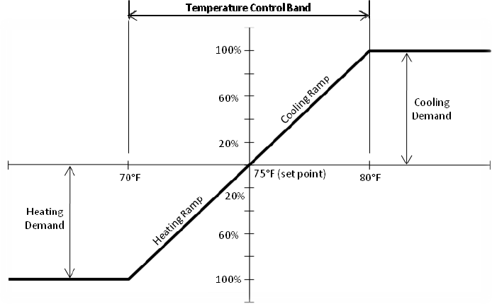
Proportional (P) Control: A setpoint and a control band are defined in the system setup. System demand
is calculated proportionate to the deviation from the setpoint, based on the control band. The demand
modulates from 0% to 100% as the measured variable moves from the setpoint to setpoint + (control
band/2). Figure 5-1 illustrates a proportional control scheme for temperature. In the example, the
control band is 10°F with a setpoint of 75°F. In the example illustrated here, at 80°F, the demand for
cooling would be 100% and at 70°F the demand for heating would be 100%. A rise of temperature of 1
above setpoint would cause a cooling demand of 20%.
Proportional-Integral (PI) Control: Proportional-integral control adds an integral term to the previous
control scheme. An additional term for the integration time also must defined in the system setup. The
integration time determines the period of history that will be considered in calculating system demand.
For example, with an integral time of 60 seconds, the deviation from setpoint over the previous 60
seconds will be taken into account when determining system demand. Total demand is then a
combination of the current measured demand (the proportional term) and historical demand (the
integral term).
A long integration time will result in sluggish controller response, while a short integration time can
result in oscillatory behavior as short-term fluctuations are magnified. If PI control is selected,
integration time will need to be adjusted in the field to dial in the controls.
24
Figure 5-1: Temperature Control Ramps for Proportional Control
The control bands for temperature and humidity are set under the ramp control menu. If proportional
integral control is used, the time period for the integral is set here as well. AboveAir Technologies units
use 8.0 and 10.0 for the default temperature and humidity bands, respectively, as shown in the screen
below.
╔════════════════════╗
║ RAMP CONTROL ║
║ TYPE Band INT║
║TEMP=P 08.0 120s║
║HUM= P 10.0 120s║
╚════════════════════╝
5.4.2 CL/HT RAMP CNTRL
Cooling and heating ramp controls are one of the means used to create dead bands around the set
point. Referring to the screen below, START defines the point where a call for cooling or heating will
begin when the temperature is moving away from set point. END defines the point where a call for
cooling or heating will cease as the temperature is moving towards the set point.
╔════════════════════╗
║ CL/HT RAMP CNTRL║
║ START END║
║COOLING= 000% 100%║
║HEATING= 000% 100%║
╚════════════════════╝
In the example shown in Figure 5-1, cooling or heating demand begins upon any deviation from the set
point. In order to create a 1°F dead band on the cooling ramp, COOLING START would be set to 20% and
COOLING END would be set to 80%.
25
5.4.3 HU/DH RAMP CNTRL
Humidify and dehumidify ramp controls operate in the same manner as the temperature controls
discussed under 5.04.2.
╔════════════════════╗
║ HU/DH RAMP CNTRL║
║ START END║
║HUMIDIFY= 000% 100%║
║DEHUMID= 000% 100%║
╚════════════════════╝
5.5 COOLING SETUP
5.5.1 COOLING SETUP
AboveAir Technologies produces units that can utilize direct expansion or chilled water coils for cooling.
The cooling setup screen is utilized to set the system TYPE to correspond to your unit's cooling method -
valve or stage - and will affect the subsequent submenus.
5.5.1.1 COOLING SETUP - CHILLED WATER SYSTEMS
For chilled water systems utilizing a modulating control valve, cooling type will be set to VALVE. With
type set to valve, 3P Valve Time must be set. 3P Valve Time is the delay for the control valve to go from
fully closed to fully open. None of the subsequent submenus will appear for chilled water systems.
╔════════════════════╗
║ COOLING SETUP ║
║TYPE=VALVE ║
║3P VALVE TIME= 060 s║
║ ║
╚════════════════════╝
5.5.1.2 COOLING SETUP - DX SYSTEMS
For DX systems, cooling type will be set to STAGE. The number of stages corresponds to the number of
compressors installed in the system, which may vary from 1 to 4 in a DX system. Unloaders per stage
can be set to 0 or 1; this value will typically be 0 for AboveAir systems.
╔════════════════════╗
║ COOLING SETUP ║
║TYPE=STAGE ║
║NUMBER OF STAGES=0 ║
║UNLOADERS/STAGE= 0 ║
╚════════════════════╝
5.5.2 COMPRESS SETUP
AboveAir's program can operate up to 4 compressors. These compressors are staged using step logic
based on the cooling demand as determined in 5.04, with ON and OFF points set under this submenu, as
shown in the example screen below. In the example screen shown below, Compressor 1 would be
activated when the cooling demand reached 40% and Compressor 2 would be activated when the

26
cooling demand reached 60%. As the cooling demand was met, Compressor 2 (if active) would be
deactivated when cooling demand fell to 15% and Compressor 1 would be deactivated when cooling
demand fell to 5%.
╔════════════════════╗
║ COMPRESS SETUP ║
║ ON OFF║
║COMPRESS 1=040 005%║
║COMPRESS 2=060 015%║
╚════════════════════╝
5.5.3 COMPRESSORS
The first COMPRESSORS submenu allows low pressure delay and minimum on & off times to be set for
the compressors. These delays are used to prevent compressor short cycling. AboveAir Technologies
ships its units with a 60 second compressor delay after a low pressure warning and with a 3 minute
minimum for the compressor on/off. NOTE: Altering these values can result in improper compressor
operation and will void the compressor warranty.
Parameter
Description
Low Press Delay
Sets a time delay for restart after a compressor suffers a low pressure
alarm.
Minimum On Time
Sets a minimum compressor run time
-
the compressor will run at
least this length of time, even if demand is met. This value is set at 3
minutes to prevent short cycling of the compressors.
Min Off Time
Sets a minimum off time, during which time the com
pressor will not
reactivate even on a call for cooling. This value is set at 3 minutes to
prevent short cycling of the compressors.
Time Bet Comps
Sets a minimum time between the activation of compressor stages
-
for example, the second compressor will not start for at least 60
seconds after the first stage has activated regardless of cooling
demand based on the sample menu screen setting.
Comp Rotation
"OFF" deactivates compressor rotation. "ON" enables compressor
rotation on a first on, first off basis.
╔════════════════════╗ ╔════════════════════╗
║ COMPRESSORS ║ ║ COMPRESSORS ║
║LOW PRESS DELAY=060s║ ║TIME BET COMPS= 060s║
║MINIMUM ON TIME=180s║ ║COMP ROTATION= OFF ║
║MIN OFF TIME= 180s║ ║ ║
╚════════════════════╝ ╚════════════════════╝
5.5.4 FREECOOL SETUP
On water or glycol cooled systems with a free cooling coil, the FREECOOL SETUP submenu defines the
operation of the coil. They can be setup to operate in one of two ways: ON UNTIL DX or ALWAYS ON.
Parameter
Description
Mode
"ON UNTIL DX" will utilize free cooling until the system's first
compressor is activated. "ALWAYS ON" will utilize the free cooling

27
coil while there is cooling demand.
On Delay
Sets a delay following unit activation during
which time the free
cooling feature will not be activiated.
Cool Ramp
Defines the range over which the free cooling coil will operate; refer
to Sections 5.4.1 and 5.5.2 for further information on the ramp and
for coordinating the staging of free cooling with compressor
operation.
╔════════════════════╗
║ FREECOOL SETUP ║
║Mode= ON UNTIL DX║
║On Delay= 600 sec ║
║Cool Ramp=000 - 025%║
╚════════════════════╝
5.6 HEATING SETUP
5.6.1 HEAT SETUP
Control type is selected on this screen. AboveAir Technologies produces units that may use hot gas
reheat, electric heating, steam heating, or hot water heating. The heat setup screen allows the type of
heat/reheat to be setup.
Additionally, OA HT DISABLE can be set on this screen. This value will disable any reheat options based
on the outdoor air temperature.
5.6.1.1 HEAT SETUP - STEAM/HEATING WATER SYSTEMS
For a system featuring a single stage of steam or heating water heat or reheat, the system TYPE will be
set to VALVE. With type set to valve, 3P Valve Time must be set. 3P Valve Time is the delay for the
control valve to go from fully closed to fully open. None of the subsequent submenus will appear for
systems with TYPE set to VALVE.
╔════════════════════╗
║ HEAT SETUP ║
║TYPE=VALVE ║
║3P VALVE TIME= 060 s║
║OA HT DISABLE= 85ºF ║
╚════════════════════╝
5.6.1.2 HEAT SETUP - STAGED SYSTEMS
For a system featuring multiple heating or reheat stages, or a system using ON/OFF type heating
elements, the system TYPE will be set to STAGE. The number of stages can be set from 0 to 4 and can
control a combination of ON/OFF heating stages combined with a modulating stage.
╔════════════════════╗
║ HEAT SETUP ║
║TYPE=STAGE ║
║NUMBER OF STAGES=0 ║
║OA HT DISABLE= 85ºF║
╚════════════════════╝
28
5.6.2 HEATER STAGES
AboveAir's program can operate up to 4 stages of heating, including a modulating stage. The various
heating components are staged using step logic based on the cooling demand as determined in 5.04,
with ON and OFF points set under this submenu, as shown in the example screen below. In the example
screen shown below, Heater 1 would be activated when the heating demand reached 40% and Heater 2
would be activated when the heating demand reached 60%. As the heating demand was met, Heater 2
(if active) would be deactivated when cooling demand fell to 15% and Heater 1 would be deactivated
when cooling demand fell to 5%.
╔════════════════════╗
║ HEATER STAGES ║
║ ON OFF ║
║HEATER 1= 040 005%║
║HEATER 2= 050 010%║
╚════════════════════╝
5.6.3 HEAT STAGE/RAMP
For systems with a modulating stage of heat, STAGE RAMP will be set to ON. This enables the heater
output to modulate the output between 0 and 100%. The modulating heating stage will typically be set
as the last stage of heating.
For systems with 2 ON/OFF stages of heating, where the elements are sized such that one is twice the
size of the other, the system can be set up for 3 stages of heating. The smaller element will be
connected to the system as Heater 1 and the larger element will be connected to the system as Heater
2. STAGE RAMP will be set to ON and STAGE TYPE will be set to 3S. The system will then control the
stages in the following pattern:
Stage 1 - Heater 1 ON, Heater 2 OFF
Stage 2 - Heater 1 OFF, Heater 2 ON
Stage 3 - Heater 1 ON, Heater 2 ON
╔════════════════════╗
║ HEAT STAGE/RAMP ║
║STAGE RAMP=OFF ║
║STAGE TYPE=2S ║
║ ║
╚════════════════════╝
5.7 HUMIDITY SETUP
AboveAir Technologies units can be used for dehumidification and may be provided with an optional
humidifier.
29
5.7.1 HUMIDITY CONTROL
For all AboveAir Technologies units, the first humidity control menu will be set up exactly as below.
AboveAir units use a separate canister humidifier for humidification and use cooling with reheat for
dehumidification.
╔════════════════════╗
║ HUMIDITY CONTROL║
║ ║
║Integr. Humidify:OFF║
║DEH= COOL/REHEAT ║
╚════════════════════╝
5.7.2 HUMIDITY CONTROL
For systems equipped with a humidifier, the set points for the humidifier relay are set in a similar
manner to the compressor and heater setpoints. ON is the percentage of demand as determined by the
humidity ramp control which will activate the humidifier relay; OFF is the percentage of demand as
determined by the humidity ramp control which will deactivate the humidifier relay.
╔════════════════════╗
║ HUMIDITY CONTROL║
║ ON OFF ║
║HUM RELAY= 040 005%║
║ ║
╚════════════════════╝
30
6 pLAN NETWORK SETUP
6.1 CONNECTING UNITS
Connection between boards in a pLAN network is carried out using an AWG20/22 shielded cable,
twisted pair plus shield. The boards are connected in parallel, with terminal J11 as the reference.
Pay ATTENTION to the network polarity: RX/TX+ on one board must be connected to RX/TX+ on the
other boards; the same is true for RX/TX-.
6.2 SAMPLE SETUP
The following steps demonstrate a setup with three units with one standby. Setup for additional units
will be similar.
6.2.1 INITIAL SETUP
1. Disconnect pLAN Cables from terminal J11 between each unit’s pCO1 I/O Boards.
2. Start with First Unit (Unit-1 / Master Unit):
a. Power-Down Unit-1 (switch main disconnect to OFF position)
b. Power-UP Unit-1 (switch main disconnect to ON position)
c. Watch the PGD Display, when the display shows *** Self-Test***, Simultaneously
HOLD-DOWN the ALRM and ↑
↑↑
↑ keys. The pLAN set-up screen will appear.
d. Using the ↑
↑↑
↑ or ↓
↓↓
↓ keys, Set the pLAN Address for the master unit to 1.
3. Repeat steps 2a-d for Unit-2, setting the pLan address to 2.
4. Repeat steps 2a-d for Unit-3, setting the pLan address to 3.
5. Power-Down all three units (switch main disconnects to OFF position) and reconnect the pLAN
wiring terminal J11 between each unit.
6. Energize / Power-UP each unit (switch main disconnects to ON position).
7. Go back to Unit-1 (MASTER UNIT)
a. After approximately 10 seconds of Unit-1 being powered-up, press and hold ↑
↑↑
↑, ↵
↵↵
↵, and ↓
↓↓
↓
simultaneously until the Display Address Setting screen appears.
b. Press ↵
↵↵
↵ once to move the flashing cursor under the Display Address Number.
c. Using the ↑
↑↑
↑ or ↓
↓↓
↓ keys, change Unit-1’s display address to 17. Press ↵
↵↵
↵ to save this
change.
i. Note: If the display goes blank, , press and hold ↑
↑↑
↑, ↵
↵↵
↵, and ↓
↓↓
↓ simultaneously again
until the Display Address Setting screen appears.
ii. Press ↵
↵↵
↵ twice to move the flashing cursor under the I/O Board Address. Using
the ↑
↑↑
↑ or ↓
↓↓
↓ keys, change Unit-1’s I/O Board Address to 01 (if it is not already).
Press ↵
↵↵
↵ to save this change. Press ↵
↵↵
↵ button to advance to Terminal
configuration screen. The parameters for Unit-1 should match the following. If
not, press ↵
↵↵
↵ button to move the flashing cursor under respective each
parameter, and use the ↑
↑↑
↑ or ↓
↓↓
↓ keys to change each value as required. Press ↵
↵↵
↵
button to save each change:

31
TRM1 to 17 PR
TRM2 to none ---
TRM3 to none --- answer OK YES
Note: Remember to press ↵
↵↵
↵ to save these changes. Press ESC as required to
return to the default display screen showing Date/Time, Unit Set Points & Status
8. Go to Unit-2
a. Follow steps 7a-c, however, set Unit-2's Display Address to 18 and I/O Board Address to
02.
TRM1 to 18 PR
TRM2 to none ---
TRM3 to none --- answer OK YES
Note: Remember to press ↵
↵↵
↵ to save these changes. Press ESC as required to return to
the default display screen showing Date/Time, Unit Set Points & Status.
9. Go to Unit-3
a. Follow steps 7a-c, however, set Unit-2's Display Address to 19 and I/O Board Address to
03.
TRM1 to 18 PR
TRM2 to none ---
TRM3 to none --- answer OK YES
Note: Remember to press ↵
↵↵
↵ to save these changes. Press ESC as required to return to
the default display screen showing Date/Time, Unit Set Points & Status.
6.2.2 MASTER UNIT SETUP (UNIT-1)
1. Press PRG.
2. Using the ↑
↑↑
↑ key, scroll to the TECHNICIAN MENU. Press ↵
↵↵
↵ to enter the Technician Menu
Password Screen.
3. Press ↵
↵↵
↵ once to move the cursor to the password. Use the ↑
↑↑
↑ key to change the password to 002
and press ↵
↵↵
↵ to enter the TECHNICIAN MENU.
4. Use the ↓
↓↓
↓ key to scroll to NETWORK SETUP. Press the ENTER button to enter the First Network
Setup screen. Using the same type of maneuvering through and value changing / saving, change
the values of the following five Network Set-Up screens as follows:
a. First Screen (Network Set-up)
╔════════════════════╗
║ NETWORK SET-UP ║
║TOTAL UNITS 3 ║
║STAND-BY UNITS 1 ║
32
║NETWORK CLOCK ON║
╚════════════════════╝
b. Second Screen (Unit Rotation)
╔════════════════════╗
║ UNIT ROTATION ║
║ ║
║DAY 1 ║
║TIME 12:00║
╚════════════════════╝
c. Third Screen (Network Alarms)
╔════════════════════╗
║ NETWORK ALARMS ║
║ ║
║SHUTDOWN NO ║
║STANDBY YES║
╚════════════════════╝
d. Fourth Screen (Network Assist)
Note: Network Assist allows standby unit to turn on to assist in the Cooling, Heating,
Dehumidifying and/or Humidifying of the space if the current two units can not handle
the room load. There must be enough power for all three units to operate
simultaneously.
╔════════════════════╗
║ NETWORK ASSIST ║
║ BAND ║
║DEH OFF 00.0 ║
║HUM OFF 00.0 ║
╚════════════════════╝
e. Fifth Screen (Network Assist)
Note: Network Assist allows standby unit to turn on to assist in the Cooling, Heating,
Dehumidifying and/or Humidifying of the space if the current two units can not handle
the room load. There must be enough power for all three units to operate
simultaneously.
╔════════════════════╗
║ NETWORK ASSIST ║
║ BAND ║
║COOL OFF 00.0 ║
║HEAT OFF 00.0 ║
╚════════════════════╝

33
7 BMS Setup
7.1 pCOWeb Serial Card (Ethernet Connection)
The pCOWeb serial card may be provided with your unit in order to allow connection to a BMS network.
It offers a variety of functions for administering your unit, including:
• BACnet/IP: Provides access to the controller for supervision software using the BACnet/IP
protocol.
• BACnet/Ethernet: Provides access to the controller for supervision software based on the
BACnet Ethernet protocol.
• Web Server: Allows access to the controller using an internet browser.
• E-mail: Send e-mail when programmable events occur.
• SNMPv1 & v2: Allows for access to the controller using software based on the SNMP protocol.
The serial card is installed at the factory; refer to the brochure included with the card if purchased
separately at a later date.
By default, the card is set-up with the following parameters:
Parameter
Factory Value
IP Address
172.16.0.1
Subnet mask
255.255.0.0
Admin user name
admin
Admin password
fadmin
Refer to the supplemental pCOWeb manual from Carel provided with your unit for a full discussion of all
of the available features. Refer to section 7.3 for a list of points (both Carel and BACnet indices)
available for integration.
The card may be configured either using the BACset tool available from http://ksa.carel.com, or by
accessing the card directly using a crossover cable. Note: to access the card via direct connection, the
connection must be set up so that the comptuer's IP address is 172.16.XX.XX (XX.XX can be anything
other than 0.1) with subnet mask 255.255.0.0.
7.2 pCONet (RS-485 Connection for BACnet)
The pCONet serial card may be provided with your unit in order to allow connection to a BMS network
(refer to your submittal documents). It allows connections via:
• BACnet/MSTP: Provides access to the controller for supervision software for using the
BACnet/MSTP protocol.
• BACnet/IP: Provides access to the controller for the supervision software using the BACnet/IP
protocol.

34
The serial card is installed at the factory; refer to the brochure included with the card if purchased
separately at a later date.
By default, the card is set-up with the following parameters:
Parameter
Min
Max
Factory
Device Instance
0
4194303
77000
Station Address
0
127
0
MaxMaster
0
127
127
Max Info Frames
0
255
20
Baud Rate
9600
-
19200
-
38400
-
76800
38400
To configure these values, an RS-485 interface is required. A USB to RS-485 adapter is available from
Carel (CVSTDUMOR0), an integral RS-485 pc card, or a serial to RS-485 adapter can be used. Download
the BACset tool from http://ksa.carel.com. Follow the directions included with the download to set the
appropriate COM port for configuration.

35
7.3 Points Lists
Description
BACnet Modbus
Carel R/W
Notes
BV=Binary Value
AV=Analog Value
Register
D=Digital
A=Analog
I=Integer
Index
R=Read
Only
W=Writable
Active Modes
Cooling Status AV1015 I 15 R 0=Off, 1-4=Qty Stages 5=Cool
Heating Status AV1051 I 51 R 0=Off, 1-4=Qty Stages, 5=heat, 6=reheat
Alarms (0=Normal, 1=Alarm)
Airflow Switch BV137 D 137 R
Compressor 1 High Pressure BV57 D 57 R
Compressor 2 High Pressure
BV60 D 60 R
Compressor 1 Low Pressure
BV149 D 149 R
Compressor 2 Low Pressure
BV148 D 148 R
Dirty Filter BV111 D 111 R
Drain Pan BV101 D 101 R
Pump Failure BV144 D 144 R
Smoke Detector BV167 D 167 R
Enables (0=Not Enabled, 1=Enabled)
Compressor 1 Enable BV56 D 56 W
Compressor 2 Enable BV59 D 59 W
Compressor Rotation BV54
D 54 W Enables First On/First Off Rotation
Dehumidification Mode Enable BV81
D 81 W
System Enable BV170
D 170 W
System On/Off
Humidifier Enable BV130
D 130 W
Heater 1 Enable BV121
D 121 W
Heater 2 Enable BV123
D 123 W

36
Description
BACnet Modbus
Carel R/W
Notes
BV=Binary Value
AV=Analog Value
Register
D=Digital
A=Analog
I=Integer
Index
R=Read
Only
W=Writable
Sensor Values
Return/Inlet Temperature AV2 A 2 R Refer to Wiring Diagram for installed sensors
Dewpoint Temperature AV90 A 90 R Refer to Wiring Diagram for installed sensors
Room Temperature AV14 A 14 R Refer to Wiring Diagram for installed sensors
Return/Inlet Humidity AV19 A 19 R Refer to Wiring Diagram for installed sensors
Setpoints
Dew point AV91 A 91 W OA Unit
Cooling AV86 A 86 W OA Unit
Humidify AV23 A 23 W OA Unit
Heat Area 1 AV92 A 92 W OA Unit
HG ReHeat AV96 A 96 W OA Unit
Temperature AV86 A 86 W Standard Unit
Humidify AV23 A 23 W Standard Unit
Statuses (0=Off, 1=On)
Compressor 1 Status BV50 D 54 R
Compressor 2 Status BV53 D 53 R
Fan Status BV33 D 33 R
Schedule Override Status BV158 D 158 R
Occupied Mode (Schedule)
BV52
D 52 R 0=Unoccupied, 1=Occupied
Heater 1 Status
BV66
D 66 R
Heater 2 Status
BV88
D 66 R
Remote On/Off
BV138
D 138 R 0=On, 1=Off by Remote Switch
System Demands
Cooling Demand AV3 A 3 R
Heating Demand AV4 A 4 R
Humidify Demand AV1 A 1 R
Dehumidification Demand AV5 A 5 R

37
8 ALARMS & TROUBLESHOOTING
This guide is provided as a supplement to the unit's IOM manual, other supplemental manuals, and
wiring diagram. Prior to troubleshooting any alarms via the controller, verify that there is not a
mechanical or electrical cause for an alarm. System alarms and lockouts are designed to protect system
components from conditions that may cause serious damage - unacceptable pressure conditions for
compressor operation, for example.
Problem
Possible Cause Checks & Solutions
No Power to Display
Cord not attached
Verify that the 6-pin cord is firmly
attached to the control board and the
display terminal
No power to unit
Refer to unit IOM manual and
troubleshoot power issues.
Fuse on control board is
blown
Check fuse at board
»If blown: replace fuse
»If not blown: contact manufacturer
Display is blank
Display address is
incorrect
Refer to section 2.5.1 to change
terminal address (no pLan) or section 6
(with pLan).
Unit off by keypad
Unit off by alarm
Verify no recent or active alarms.
»If active alarm: troubleshoot alarm
prior to re-enabling the unit. Refer to
section 3.3 to re-enable unit after
clearing alarm.
Unit off by manual control Refer to section 3.3 to re-enable unit.
No Cooling, Heating, or
Humidification
No call for cooling Verify setpoints and adjust as required.
System/components off
following alarm
Verify all system alarms have been
addressed. After addressing any
alarms, refer to section 3.3 to re-
enable system/components.
